
Stent having improved stent design

a stent and design technology, applied in the field of stents having improved stent design, can solve the problems of tissue change, significant negative impact on the mechanical properties of the stent, and subsequent increased formation of new tissue (neointimal proliferation), and achieve the effect of effectively utilizing the space available for crimping

Active Publication Date: 2012-04-26
BIOTRONIK AG
View PDF2 Cites 39 Cited by
  • Summary
  • Abstract
  • Description
  • Claims
  • Application Information

AI Technical Summary

Benefits of technology

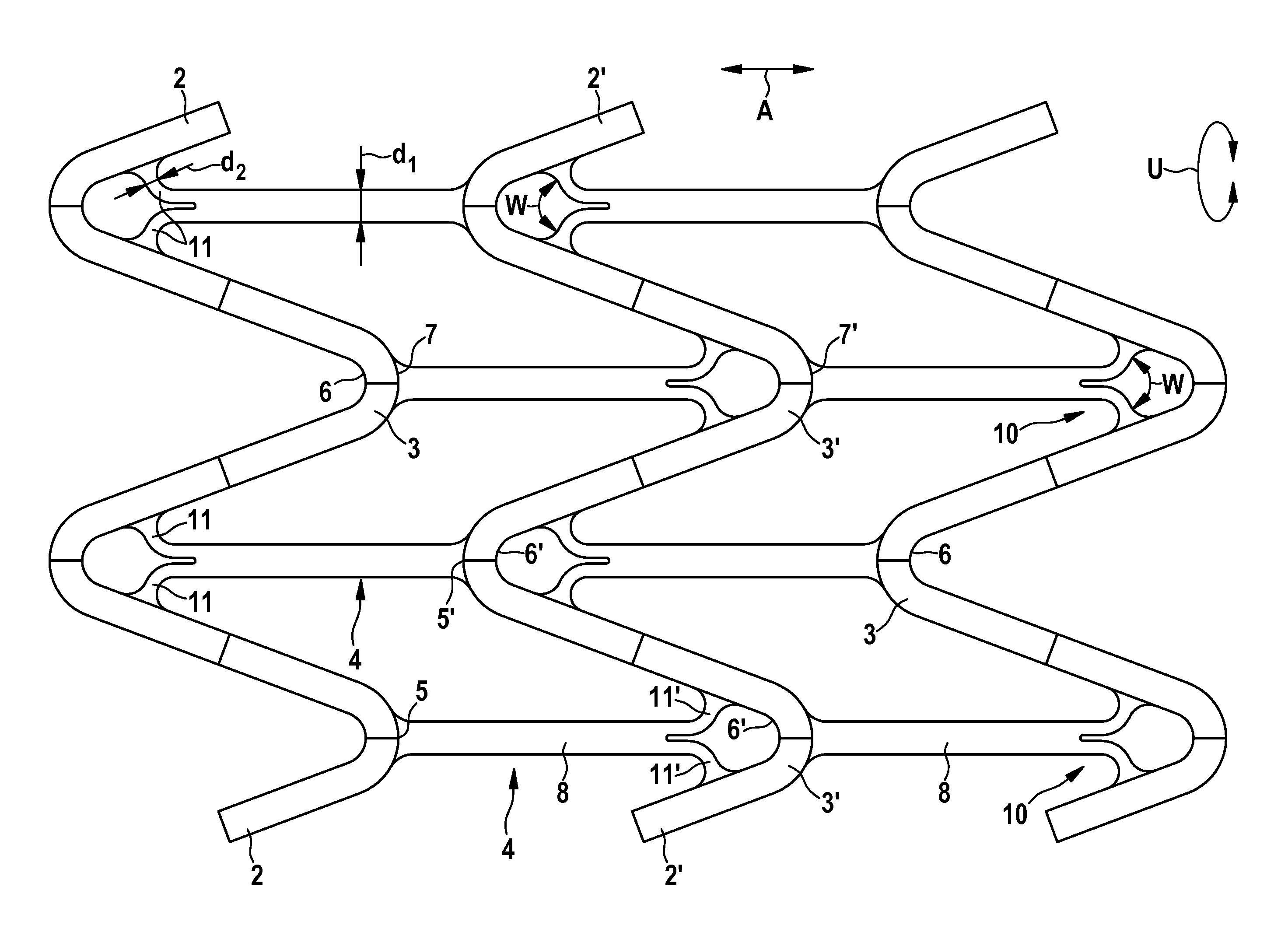
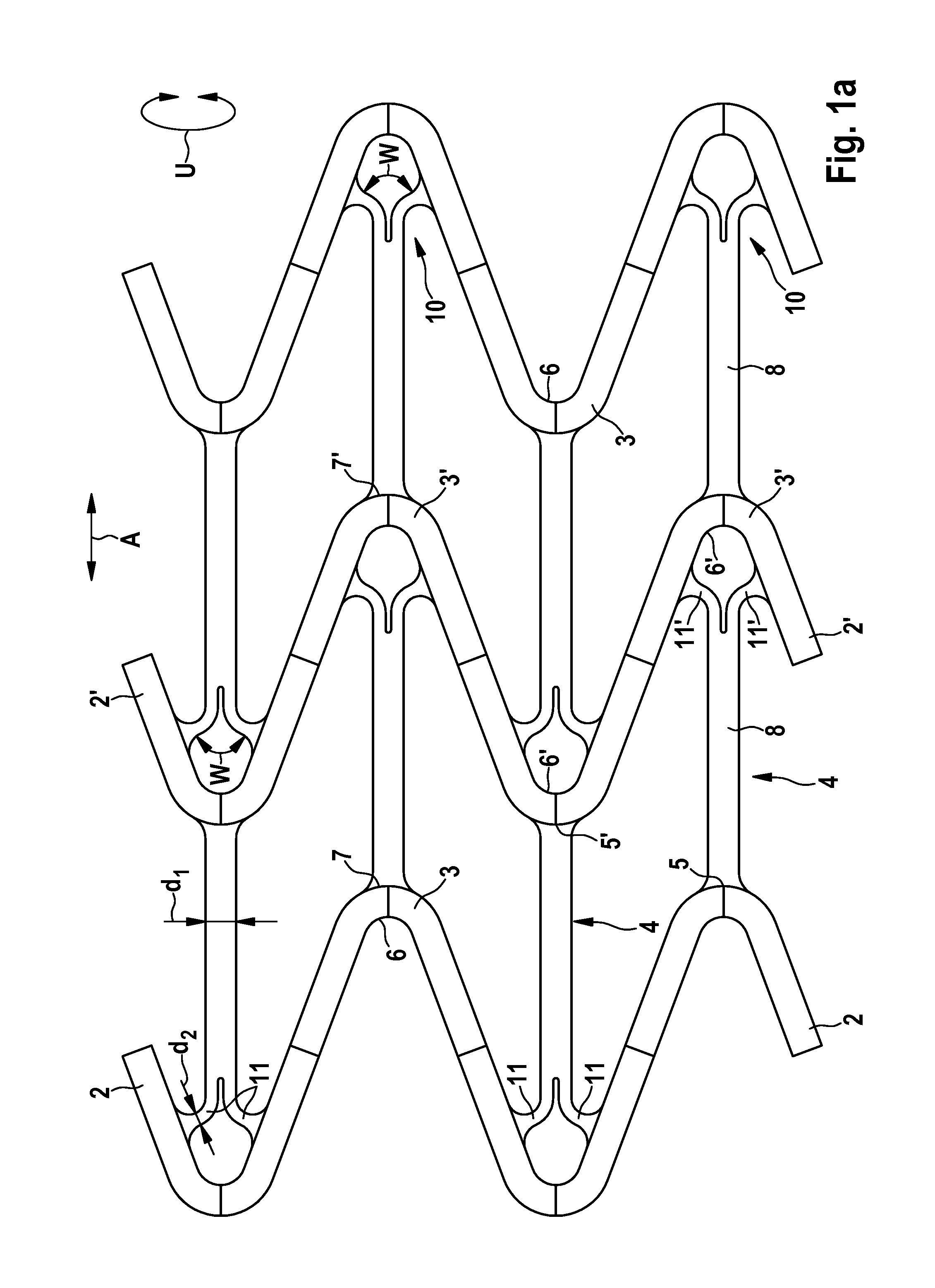
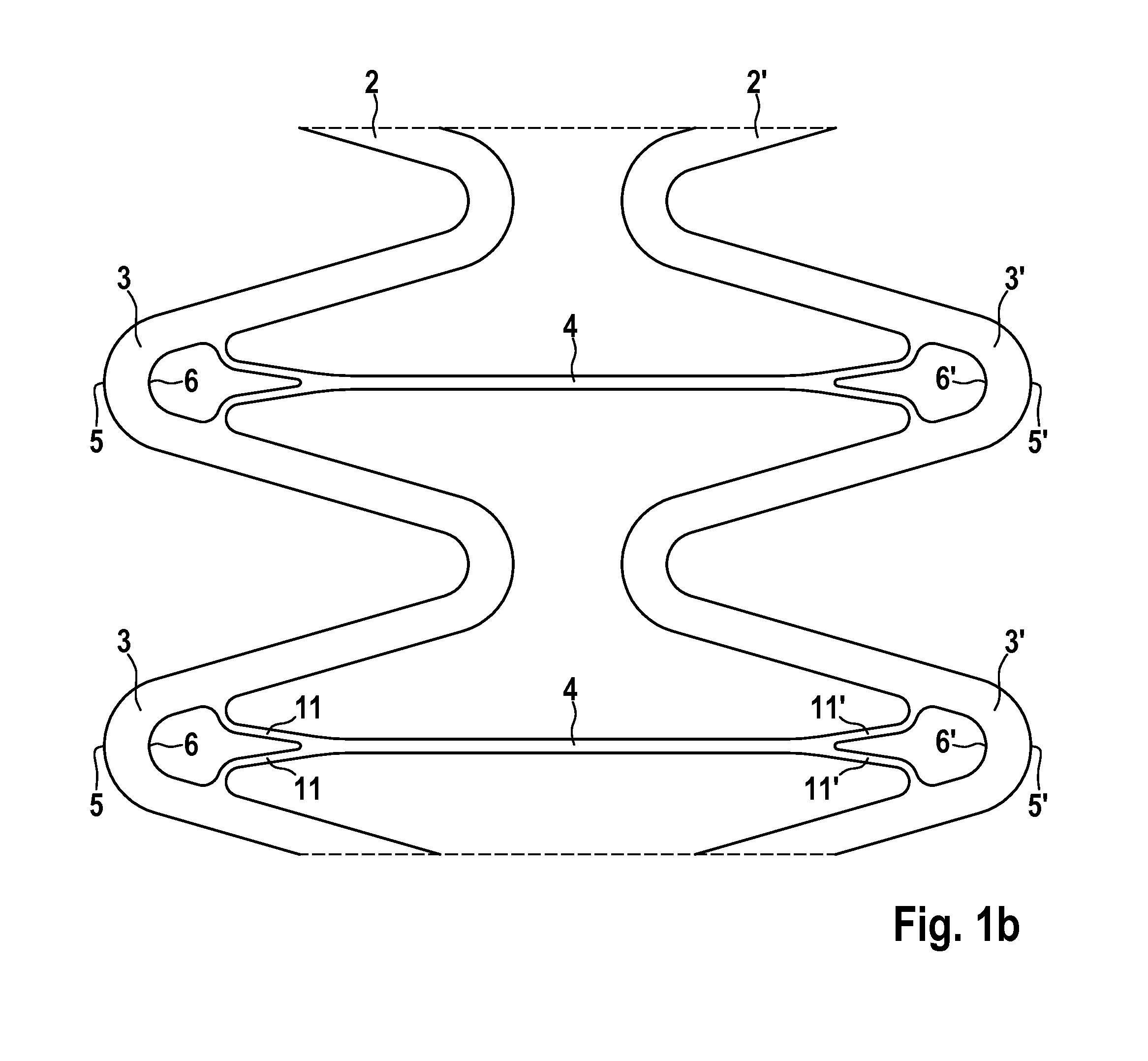
The present invention provides a stent design that minimizes the impact on the distribution of forces in the supporting struts while effectively utilizing space during crimping and bending flexibility. The stent has a base body circumscribing a cylindrical shape and is radially expandable from a contracted starting position. The stent includes a plurality of meander-shaped struts disposed in the circumferential direction and arrayed on one another in the axial direction. The at least one axial connector joining the meander-shaped struts has a double-arm structure that allows for homogeneous plastic deformation and reinforcement of the stent. The stent design ensures optimal distribution of forces and minimal recoil of the stent. The at least double-arm structure includes a plurality of arms that enclose an angle in the range of -30° to 180°. The base body of the stent may be made of any implantation material suitable for the production of implants, such as metallic materials, polymers, and ceramic materials.

Problems solved by technology

Irritations and inflammations may occur at relatively short notice and cause tissue changes.
While the apertures in this stent design only minimally affect crimpability, they hinder homogenous plastic deformation of the support elements and thus have a significant negative impact on the mechanical properties of the stent.
This overdilatation causes the vessel to be overstretched so that vessel damage occurs, causing the body to respond with an inflammatory reaction and subsequent increased formation of new tissue (neointimal proliferation).

Method used


Image

  • Stent having improved stent design
  • Stent having improved stent design
  • Stent having improved stent design

Examples


Embodiment Construction

[0028]The invention will subsequently be explained in greater detail on the basis of the exemplary embodiments in conjunction with the figures.

[0029]A stent has a base body circumscribing a cylindrical shape and enclosing a lumen along an axial direction. Upon implantation of the stent into a blood vessel, the blood flow can be effected through this lumen. The base body includes a plurality of meander-shaped struts disposed in the circumferential direction and arrayed on one another in the axial direction, each strut being meander-shaped in its coarse structure and made of a flexible material. The meander-shaped struts are substantially responsible for the support function of the stent. The necessary expansion of the stent base body upon stent implantation is ensured by the meandering shape of the struts.

[0030]The meandering shape has zenith points alternating their direction of curving in the course of the meander-shaped strut. A right curve is followed by a left curve, with a shor...


PUM


Abstract

A stent is provided having a base body circumscribing a cylindrical shape and radially expandable from a contracted starting position into a dilated support position, including a plurality of meander-shaped struts disposed in the circumferential direction and arrayed on one another in the axial direction, each strut being meander-shaped in its coarse structure and made of a flexible material, and at least one axial connector in the axial direction, connecting the meander-shaped struts of two axially adjacent meandering curves, wherein the at least one axial connector connects the inside radius of a zenith point of a first meandering curve with a second meandering curve, characterized in that the at least one axial connector at the inside radius of the zenith point of the first meandering curve has an at least double-arm structure.

Description

CROSS REFERENCE TO RELATED APPLICATIONS[0001]This invention is a continuation of U.S. patent application Ser. No. 12 / 777,644, filed May 11, 2010, which itself claims benefit of priority to U.S. provisional patent application Ser. No. 61 / 218,999, filed on Jun. 22, 2009, now expired; the contents of each are herein incorporated by reference in their entirety.FIELD OF THE INVENTION[0002]The invention relates to a stent having improved stent design.BACKGROUND OF THE INVENTION[0003]Implantation of stents has become established as one of the most effective therapeutic measures for treatment of vascular diseases. Stents assume a supporting function in the hollow organs of a patient. Stents of conventional construction have a base body with a plurality of circumferential support structures. For example, metallic struts have a base body which is initially in a compressed form for insertion into the body and then is dilated at the site of use. One of the main areas for use of such stents is f...

Claims


Application Information

Patent Timeline
Patent Type & Authority Applications(United States)
IPC IPC(8): A61F2/82
CPCA61F2/91A61F2/915A61F2002/91541A61F2002/91583A61F2002/91566A61F2002/91575A61F2002/91558
Inventor MEWS, STEFFENBAKCZEWITZ, FRANK
Owner BIOTRONIK AG
Learn More