Floor construction with variable grade of resilience

Inactive Publication Date: 2012-04-26
KONINKLIJKE PHILIPS ELECTRONICS NV
View PDF22 Cites 6 Cited by
  • Summary
  • Abstract
  • Description
  • Claims
  • Application Information

AI Technical Summary

Benefits of technology

[0034]By providing a gas as a fluid, it is possible to change the pressure of the medium rather quickly, which leads to a rather quick change of the flexibility of the floor construction. This can be of advantage in cases where the use of the floor requires a quick change of softness. For example, during an operation in an examination room of a hospital, different operators with individual requirements concerning the floor softness may change their position in respect to the patient during the operation and hence they will stand on different areas during the procedure. Once they change their location the new floor area where they will be standing for a longer time can then be quickly adapted by providing a floor surface in that area with a required softness. Another example is the sudden need for rolling equipment across the floor to the patient on the operation table. Then, the floo

Problems solved by technology

But it has shown that these mats have disadvantages that lead to regular complaints.
For exampl

Method used


Image

  • Floor construction with variable grade of resilience
  • Floor construction with variable grade of resilience
  • Floor construction with variable grade of resilience

Examples


Embodiment Construction

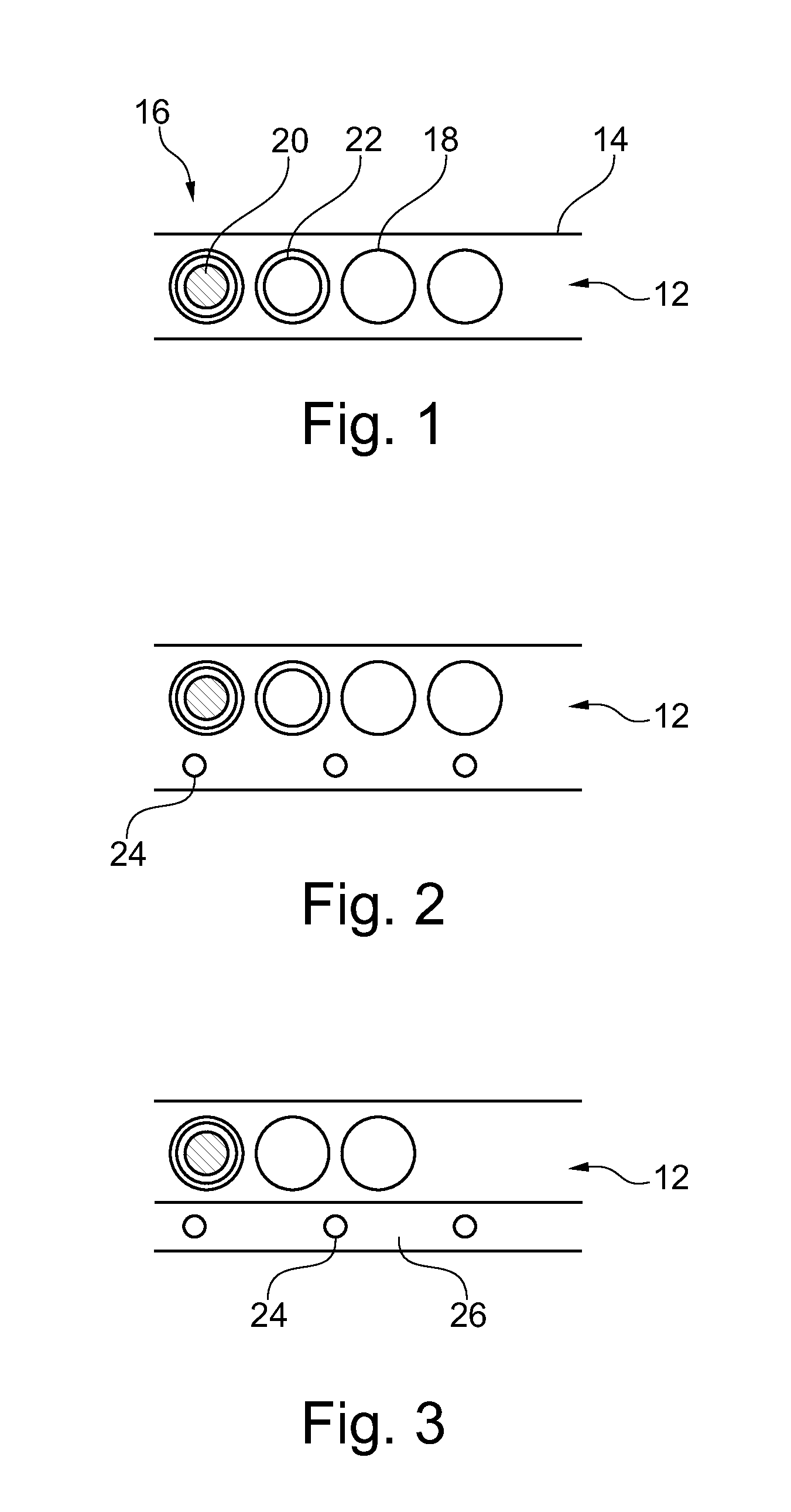
[0075]FIG. 1 schematically shows a section through a floor construction with a resilient layer 12 with a variable resilience and an adapting surface 14. Further, means 16 are provided for varying the grades of resilience. Therefore, in FIG. 1 the resilient layer 12 comprises a cavity structure with a number of cavities 18.

[0076]The cavities 18 are filled with a medium 20 with a variable flexibility. The flexibility of the medium 20 can be modified by means which are not shown in FIG. 1 but which are described further below in relation with other embodiments. In FIG. 1 the medium 20 with a variable flexibility is enclosed in a number of containers 22 with a flexible, non-expandable envelope.

[0077]By providing the medium inside such a container 22 the container itself can either act as a flexible element in case the medium is modified to be flexible itself. To provide certain stiffness, the medium 20 is modified to be stiff or at least harder than in the state when it is flexible, the...


PUM


Abstract

The present invention is related to a floor construction. To provide a floor that is able to serve the different aspects of the use and the user himself, in particular to aspects related to longer standing periods, a floor construction is proposed that comprises a resilient layer (12) with a variable resilience and an adapting surface (14) and means for varying the grade of resilience. In one exemplary embodiment the resilient layer (12) comprises a cavity structure with a number of cavities (18). The cavities (18) are filled with a medium (20) with a variable flexibility. The medium (20) is enclosed in a number of containers 22 with a flexible, non-expandable envelope and the flexibility of the medium can be modified.

Description

FIELD OF THE INVENTION[0001]The present invention is related to a floor construction.BACKGROUND OF THE INVENTION[0002]Floor constructions are usually designed for a determined purpose. Hence, their characteristics, i.e. their different parameters, such as physical strength, softness, haptics or feel of the surface, aesthetic appearance etc, are set according to the determined purpose. Concerning the constructive characteristics, floor constructions are provided in a rather static manner. Simply said, a built floor construction usually rests in the same place with the same characteristics for a rather long term. A change of the floor construction and a change of the floor characteristics are only carried out in case of a change in the use of the floor construction or in case the floor surface is worn out or destroyed somehow that makes a replacement necessary. In any case, the floor construction is always subject to the use of the floor. The use of the floor is defined by the use of ...

Claims


Application Information

Patent Timeline
IPC IPC(8): G05B13/00E04F15/22
CPCE04F15/02A47G27/0231
Inventor DATEMA, CORNELIS PAUWEL
Owner KONINKLIJKE PHILIPS ELECTRONICS NV
Why Eureka
Try Eureka