Rolling process and relating longitudinal, multi-stand rolling mill of continuous, restrained type for hollow bodies

Active Publication Date: 2012-05-03
DANIELI & C OFF MEC SPA
View PDF4 Cites 4 Cited by
  • Summary
  • Abstract
  • Description
  • Claims
  • Application Information

AI Technical Summary

Benefits of technology

[0025]Therefore the object of the present invention is to overcome all the aforesaid drawbacks and to indicate a rolling process and relating devices adapted to carry out it, so as to overcome the limits of each type of rolling mill described above, therefore to obtain a rolling mill having high productivity which is characterized, however, by a high quality standard of the pipe produced.

Problems solved by technology

In contrast, this type of rolling mill is subject to various drawbacks.
The spindle acceleration causes states of compression in the pipe, damaging to the size quality and the defectiveness of the pipes as the throat delimited by the rolling rollers is clogged (known state of “overfilling”) in the first stands and is choked (known state of “underfilling”) on the finishing stands.
There are problems of rolling stability and of excessive tolerances: the pipe cooling is not uniform over the length: the head part where there is no spindle remains hot longer, while the back part where the spindle is still inserted, is partially cooled down by the spindle itself, therefore a fossil furnace is normally required downstream to render the temperature of the pipe uniform before the final rolling required to calibrate or reduce the diameter of the pipe.
In contrast, equivalent problems are found as in the preceding case, in terms of pipe temperature non-uniformity.
This type of solution includes dragging the hot spindle by means of pressure rollers with risk of damaging the surface itself.
However, passing the spindle through the extracting rolling mill also requires a stand solution which may be quickly and precisely opened and closed, with a risk of misaligning the edges of the two adjacent rollers and therefore longitudinally marking the pipe.

Method used


Image

  • Rolling process and relating longitudinal, multi-stand rolling mill of continuous, restrained type for hollow bodies
  • Rolling process and relating longitudinal, multi-stand rolling mill of continuous, restrained type for hollow bodies
  • Rolling process and relating longitudinal, multi-stand rolling mill of continuous, restrained type for hollow bodies

Examples


Embodiment Construction

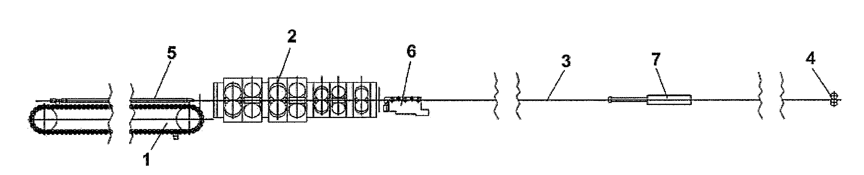
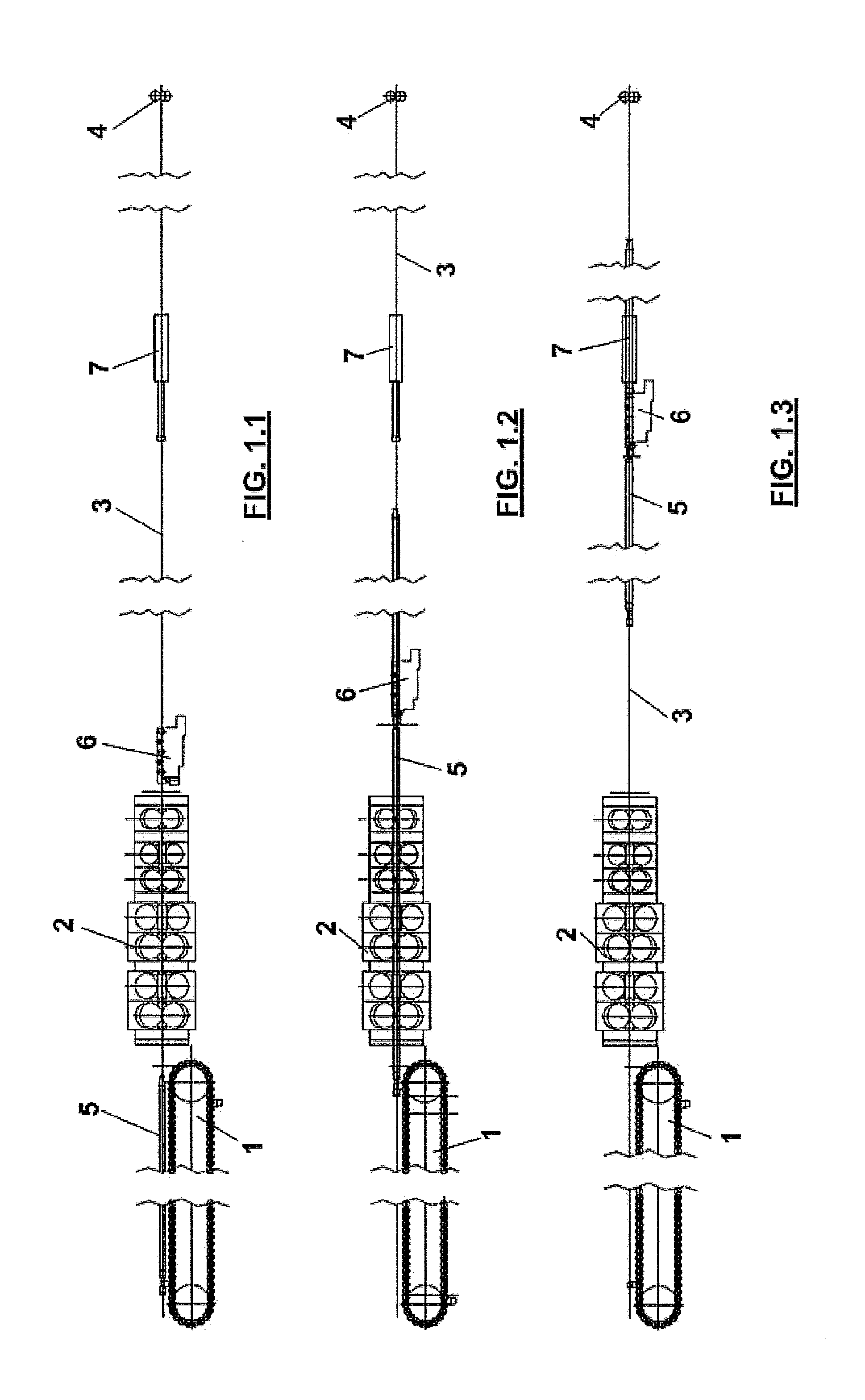
[0037]According to the main aspects of the present invention, the longitudinal, multi-stand rolling mill mainly includes (see FIGS. 1.1, 1.2, 1.3) an inlet system 1 for pipe and spindle, followed by a rolling mill 2, downstream of which is an outlet system 3 for pipe and spindle, and finally an extracting rolling mill 4 placed at a distance from the rolling mill 2 larger than the maximum length possible for the pipe being processed and for the spindle.

[0038]More precisely, the distance between the axis of the last stand of the rolling mill 2 and the axis of the first stand of the extracting rolling mill 4 is the distance between rolling mill 2 and extracting rolling mill 4.

[0039]Thereby, when the pipe is released from the rolling mill 2, the pipe is not yet engaged with the extracting rolling mill 4, thus allowing the inlet speed of the pipe into the extracting rolling mill to be independent from the outlet speed from the rolling mill, and thus possibly ending processing the pipe in...


PUM

PropertyMeasurementUnit
Lengthaaaaaaaaaa
Speedaaaaaaaaaa

Abstract

A longitudinal, multi-stand rolling mill of the continuous, restrained type for rolling hollow bodies is described, which comprises a main rolling mill (2) and an extracting rolling mill (4) in line and downstream of the main rolling mill, at a distance from the main rolling mill larger than the maximum length of the hollow body and of the spindle, and in which the spindle is extracted at the outlet of the main rolling mill in the gap between said main rolling mill and extracting rolling mill, and is laterally unloaded.

Description

FIELD OF APPLICATION OF THE INVENTION[0001]The present invention relates to the field of longitudinal rolling mills for hollow bodies operating with internal tool, and more precisely to a rolling process and relating longitudinal, multi-stand rolling mill for hollow bodies operating on a spindle.State of the Art[0002]The longitudinal, multi-stand rolling mills of known type are divided in the following types, according to their morphology with particular regard to controlling the speed is and position of the spindle within the hollow body (pipe).[0003]Floating Spindle Rolling Mill.[0004]In so-called continuous rolling mills having a floating (free) spindle, the spindle may freely move within the pipe depending on the frictional forces which are generated, and therefore it naturally accelerates as the stands are sequentially engaged. The withdrawal of the spindle from the pipe occurs out of the rolling line.[0005]Very short cycle times and thus high productivity, e.g. 4-5 pieces per ...

Claims


Application Information

Patent Timeline
IPC IPC(8): B21B1/00
CPCB21B17/14B21B23/00B21C45/00B21B25/02B21B25/00
Inventor CERNUSCHI, ETTORELATTANZI, MAURO
Owner DANIELI & C OFF MEC SPA
Why Eureka
Try Eureka