

Automated Analyzer with Low-Pressure In-Line Filtration
- Summary
- Abstract
- Description
- Claims
- Application Information
AI Technical Summary
Benefits of technology
Problems solved by technology
Method used
Image

Examples
Embodiment Construction
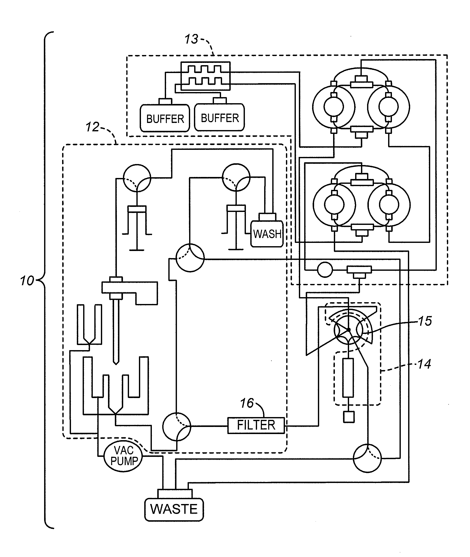
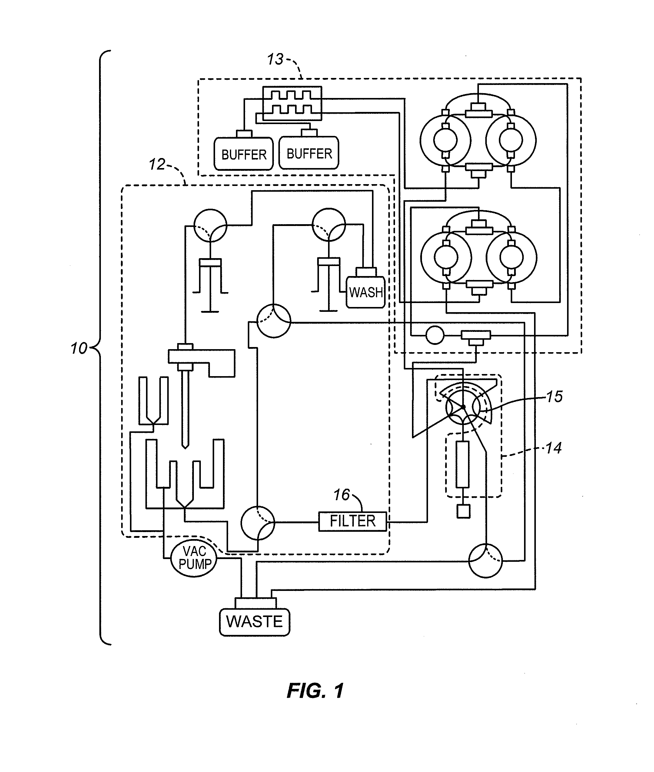
[0023]FIG. 1 is a diagram of the flow system architecture for one example of an automated blood sample analyzer 10 in accordance with the present invention. Three sections are outlined in dashed lines: a low-pressure section 12, a high-pressure section 13, and an analytical section 14. A switching valve 15 is also shown, and a sample filter 16 is shown in the low-pressure section 12.
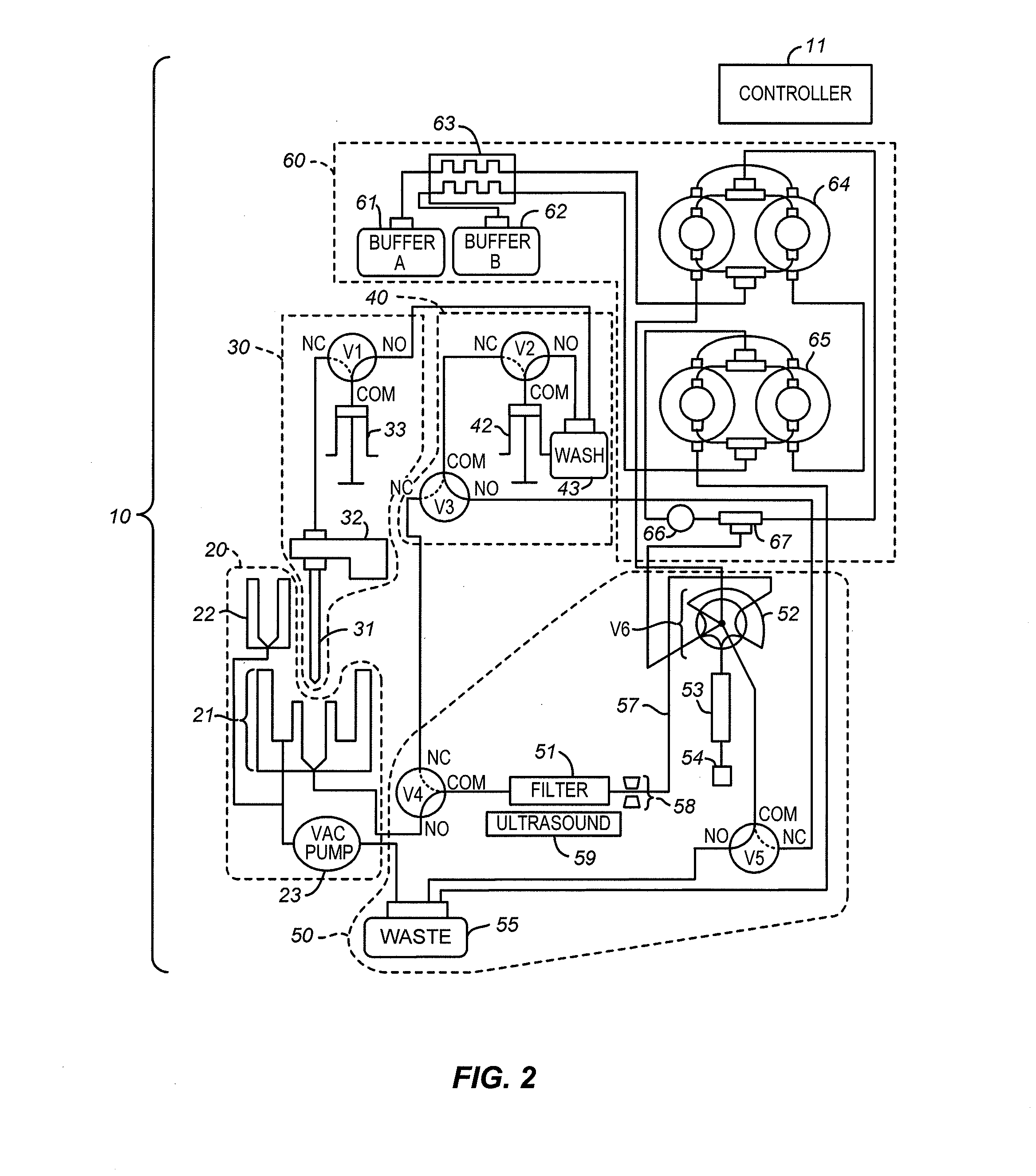
[0024]The flow system is shown in greater detail in FIG. 2 where the analyzer components are grouped into subsystems and a controller 11 which controls all valves, sensors, pumps, and detectors of the analyzer is included. The subsystems include a sample dilution subsystem 20, a sample transfer, or needle, subsystem 30, a low-pressure pump subsystem 40, an analytical cartridge subsystem 50, and a high-pressure pump subsystem 60. The controller 11 can be a general purpose computer, a purpose-built computer, or a remote server. The controller 11 in this example includes both hardware and software, and can ...
PUM
 Abstract
Description
Claims
Application Information