Subsea leak-detecting system

a leak detection system and subsea technology, applied in the field of can solve the problems of faulty detection, prior art leak detection systems do not allow for suitable and secure locations for precise detection, and prior art subsea leak detection systems cannot be easily installed, etc., and achieve the effect of simple construction

Active Publication Date: 2017-05-16
AKER SOLUTIONS AS
View PDF15 Cites 0 Cited by
  • Summary
  • Abstract
  • Description
  • Claims
  • Application Information

AI Technical Summary

Benefits of technology

[0020]The principal object of the present invention is to provide a subsea leak detection system which is adapted to be precisely and securely installed at a suitable subsea location, by virtue of its simple and unique construction, for precise detection of leakage of hydrocarbons and other materials.
[0021]It is another object of the present invention to provide a subsea leak detection system which is simple in construction comprising mutually balanced components, easy to install and very cost effective, without compromising on accuracy.
[0023]It is also an object for the present invention to provide a leak detection system that will not transfer impact forces to the subsea structure of the protective structure is hit by falling objects or otherwise subject to excessive forces.
[0024]Another object of the present invention is to provide a subsea leak detection system which can be easily accessed for example by an ROV, for installation and for retrieval after completion of operation or for maintenance / replacement.

Problems solved by technology

However, such positioning results in faulty detection, in as much as leakage of hydrocarbons such as oil and gas above the X-mas tree are not detected.
Further, the construction of such prior art leak detection systems does not allow for suitable and secure location for precise detection.
Additionally, due to their constructional disadvantage, prior art subsea leak detection systems cannot be easily installed, or for that matter retrieved after installation, for maintenance or replacement.
This is for example, due to the limited space between the X-mas tree roof and X-mas tree, the desired location of installation.

Method used


Image

  • Subsea leak-detecting system
  • Subsea leak-detecting system
  • Subsea leak-detecting system

Examples


Embodiment Construction

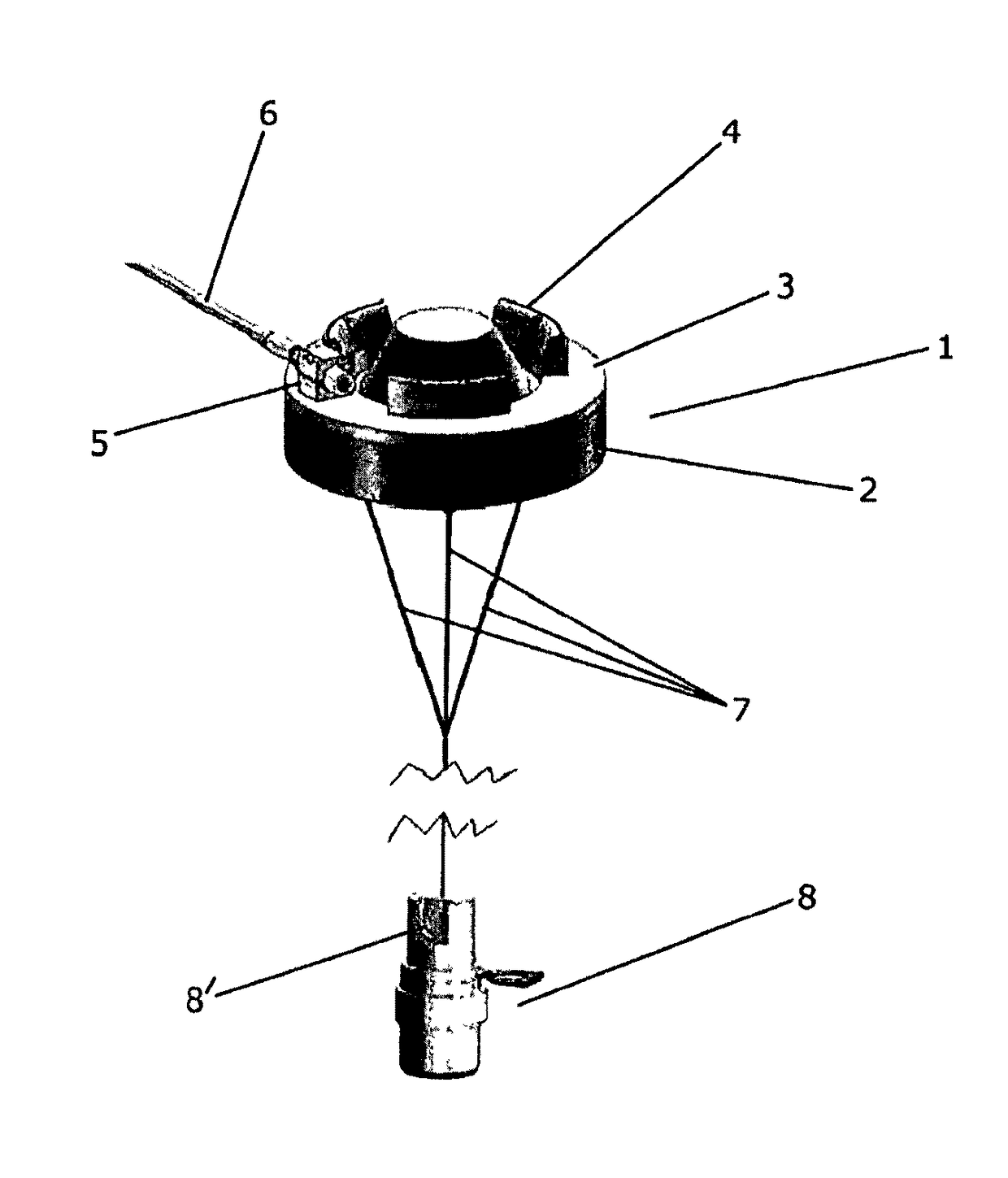
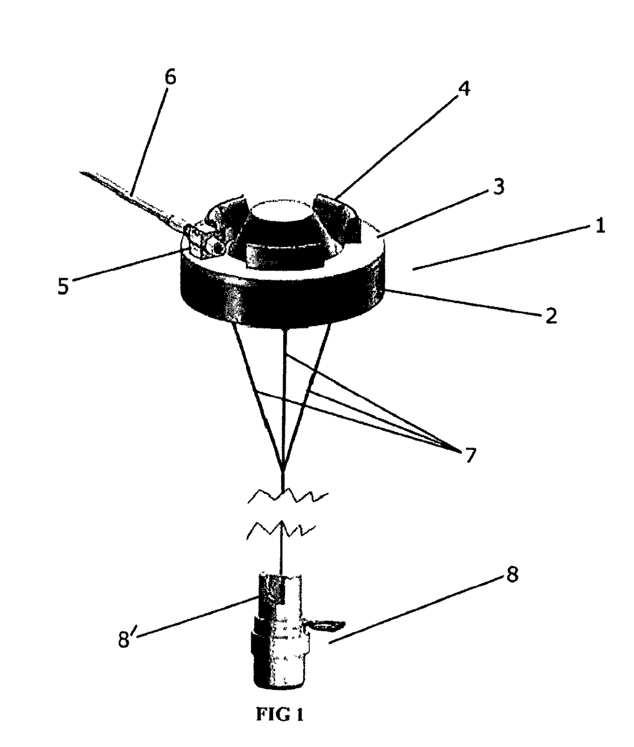
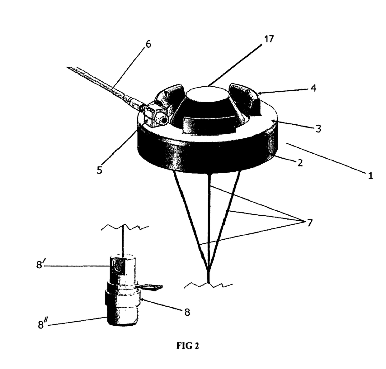
[0042]The following provides a detailed non-limiting description of a preferred embodiment of the leak detection system according to the present invention which is purely exemplary and non-limiting.

[0043]In the above context, it is hereby clarified that hereinbefore and hereinafter, the present invention as well its technical background, prior art already known, are explained with reference to hydrocarbons and X-mas trees. It should be understood that these are all limitations for the sake of explanation. The present invention pertains to all types of leakage detection under water such as hydrocarbons, hydraulic fluids / chemicals and so on, or any fluid whose Specific Gravity is lower than sea water. Further, the present invention is applicable in respect of all types of units, installations, equipments and subsea assemblies such as X-mas trees, production manifolds and so on, as known to persons skilled in the art, involved in hydrocarbon recovery by offshore operations. Reference t...


PUM

PropertyMeasurementUnit
dielectric constantaaaaaaaaaa
buoyancyaaaaaaaaaa
specific distanceaaaaaaaaaa

Abstract

A subsea leak detection system for an off-shore operation facility includes a leak detector operatively connected to a controller located on a subsea assembly. The system is provided with a floating member on which the leak detector is suitably attached. The floating member is adapted to be installed and stably positioned, above the assembly.

Description

FIELD OF THE INVENTION[0001]The present invention in general, relates to a subsea leak detection system and to a method for installation thereof.[0002]More specifically, the present invention relates to a subsea leak detection system which is adapted to be precisely, securely and conveniently positioned at an appropriate sub sea location. This facilitates precise detection of hydrocarbon and other leakage from a subsea assembly, such as a X-mas tree. Hence, is achieved triggering of a message to the well supervising team for initiating corrective steps.[0003]More particularly, the present invention relates to a subsea leak detection system and to a method of positioning such leak detection system appropriately in a subsea location.TECHNICAL BACKGROUND OF THE INVENTION[0004]It is known in the art that various subsea assemblies are applied in the exploration and production of hydrocarbons such as oil and gas. These include complex installations with various equipment and assemblies. S...

Claims


Application Information

Patent Timeline
Patent Type & Authority Patents(United States)
IPC IPC(8): E21B47/00E21B43/01F17D5/02G01M3/00G01M3/16E21B47/01E21B47/10G01N33/18
CPCE21B47/1025E21B43/01E21B43/0122E21B47/00E21B47/01E21B47/10E21B47/102F17D5/02G01M3/00G01M3/007G01M3/16G01N33/1826E21B47/113F17D5/06E21B47/117E21B47/001
Inventor ALBINSSON, BENGT-.ANG.KELUNDHEIM, LARS TIMBERLIDSTENSGAARD, ROY
Owner AKER SOLUTIONS AS
Why Eureka
Try Eureka