Automated Dilution For Liquid Chromatography

Active Publication Date: 2012-05-03
WATERS TECH CORP
View PDF10 Cites 23 Cited by
  • Summary
  • Abstract
  • Description
  • Claims
  • Application Information

AI Technical Summary

Benefits of technology

[0008]In yet another aspect, the invention features a system for injecting a diluted sample in a liquid chromatography system. The system includes a sample source, diluent source, control module, fluid combiner and injection valve. The sample source and diluent source supply sample and diluent, respectively, during a dilution time. The control module is in communication with the sample source and the diluent source to control the first flow rate, the second flow rate and the dilution time. The fl

Problems solved by technology

For example, a system may not be capable of injecting a sufficiently small quantity of sample (e.g., picoliters) to avoid a mass overload condition for the chromatography column.
Alternatively, the native solvent containing the sample may be inappropriate for the stationary phase due to a physical property (e.g., pH level) of the solvent.
In another example, the sample may be dissolved in a strong solvent that interacts with the stationary phase, leading to ambiguous results in the chromatogram.
Dilutions can be

Method used


Image

  • Automated Dilution For Liquid Chromatography
  • Automated Dilution For Liquid Chromatography
  • Automated Dilution For Liquid Chromatography

Examples


Embodiment Construction

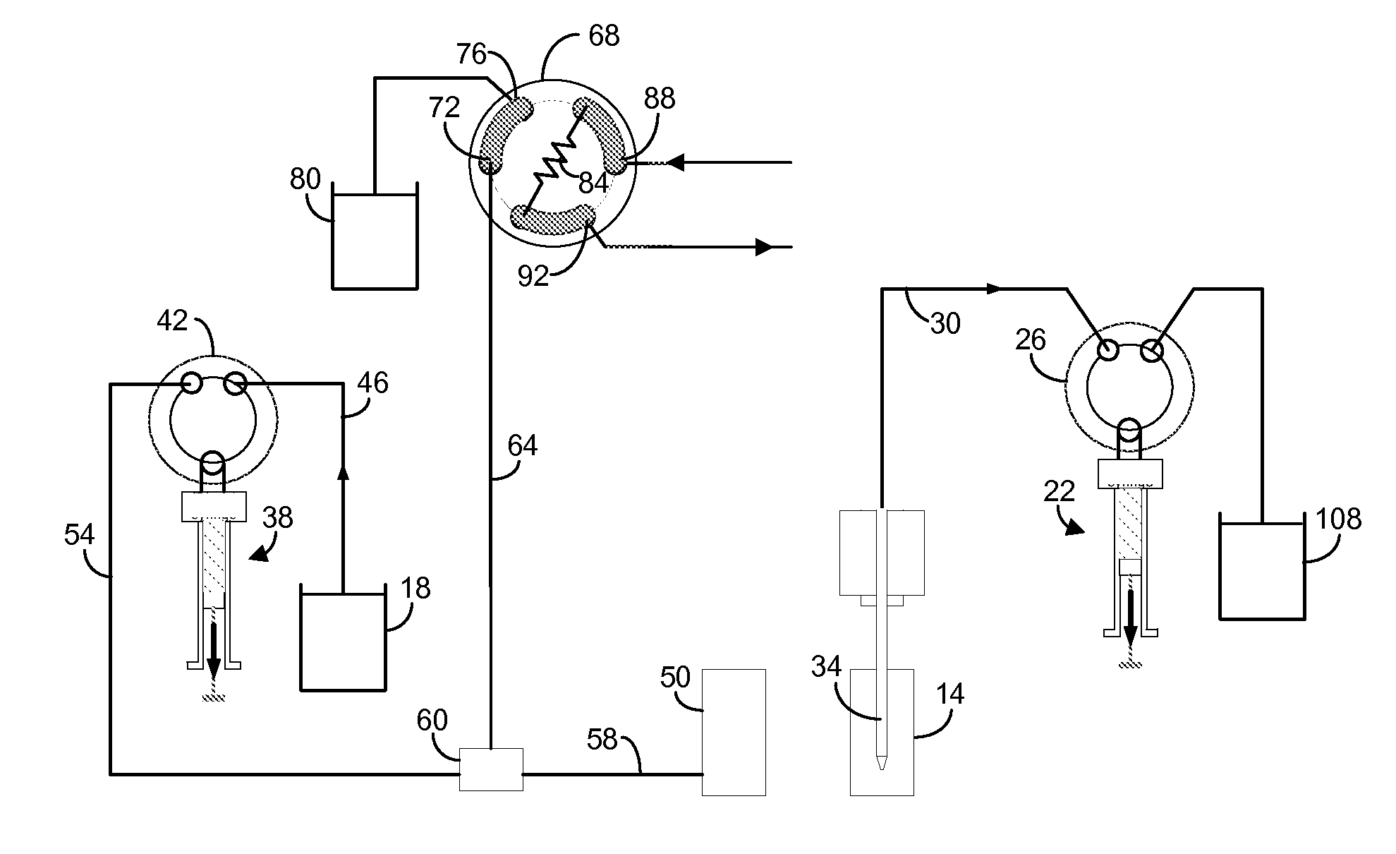
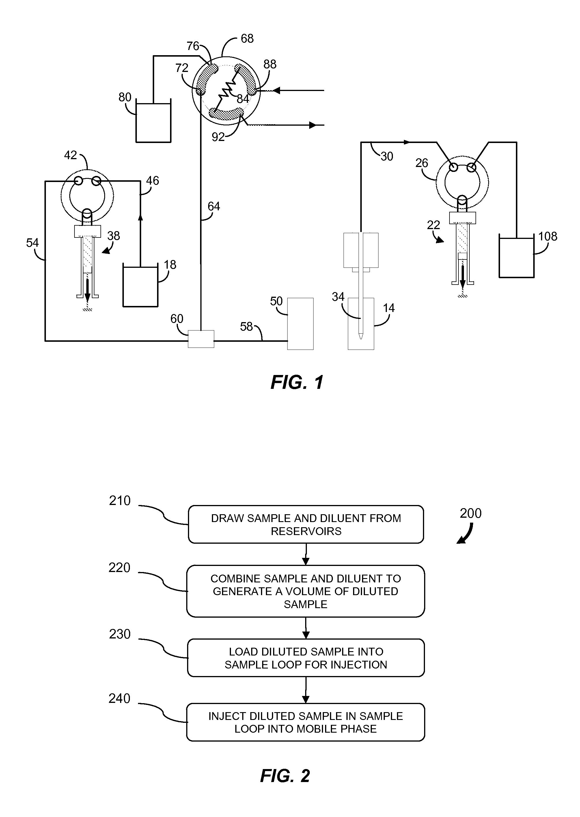
[0018]In brief overview, the invention relates to a method of diluting a sample in a liquid chromatography system. A sample flowing at a sample rate and a diluent flowing at a diluent rate are combined for a certain time to generate a volume of diluted sample. A portion of the volume is loaded into a sample loop of an injection valve and subsequently injected into a mobile phase flowing to a chromatography column. The method reduces the amount of sample wasted in conventional dilution processes for liquid chromatography.

[0019]FIG. 1 is a schematic illustration of a portion of a liquid chromatography system according to an embodiment of the invention. The system includes a sample reservoir 14 and diluent reservoir 18. The sample reservoir 14 can be a vial or other container that holds a quantity of sample to be injected into a chromatography column (not shown) after dilution. Similarly, the diluent reservoir 18 can be a container that holds a quantity of diluent used to dilute the sa...


PUM


Abstract

Described are a method and system for diluting a sample in a liquid chromatography system. A sample flowing at a first flow rate is combined for a predetermined time with a diluent flowing at a second flow rate to generate a volume of diluted sample. The diluted sample has a dilution ratio determined according to the two flow rates. A portion of the volume is loaded into a sample loop of an injection valve and subsequently injected into a mobile phase flowing to a chromatography column. The method eliminates the need to have a technician available to perform dilutions or to transfer the sample to a remote location for dilution. Advantageously, manufacturing or processing downtime to perform the dilution is not required and the amount of sample flowing to waste is reduced.

Description

CROSS REFERENCE TO RELATED APPLICATIONS[0001]This application claims priority to and benefit of U.S. Provisional Application No. 61 / 156,040, filed Feb. 27, 2009, the contents of which are expressly incorporated herein by reference in their entirety.FIELD OF THE INVENTION[0002]The invention relates generally to liquid chromatography systems. More particularly, the invention relates to a method for conveniently and efficiently diluting a sample for injection into a mobile phase in a liquid chromatography system.BACKGROUND OF THE INVENTION[0003]High pressure liquid chromatography (HPLC) systems sometimes require that a sample be diluted before it is injected into the mobile phase flowing to a chromatography column. Various reasons exist for diluting the sample prior to injection. For example, a system may not be capable of injecting a sufficiently small quantity of sample (e.g., picoliters) to avoid a mass overload condition for the chromatography column. Alternatively, the native solv...

Claims


Application Information

Patent Timeline
IPC IPC(8): G01N30/20
CPCF04B13/02G01N30/20F04B23/06G01N1/38G01N1/40
Inventor CORMIER, SYLVAINANDREWS, RICHARD W.TACCONI, ROBERTDOBBS, CRAIG H.
Owner WATERS TECH CORP
Why Eureka
Try Eureka