Reinforced extruded tubing for telescopic handle for trolley-type carry case and carry case incorporating same

a technology of extruded tubing and trolley type, which is applied in the direction of manufacturing tools, wing knobs, furniture parts, etc., can solve the problems of metal tubes adding unwanted additional cost and excessive weight to the entire case, and elongating and worn apertures, if provided in plastic tubes, and increasing production costs

Inactive Publication Date: 2012-05-03
BRIGGS & RILEY TRAVELWARE
View PDF13 Cites 35 Cited by
  • Summary
  • Abstract
  • Description
  • Claims
  • Application Information

AI Technical Summary

Benefits of technology

[0021]In particular, the metal insert strips contain apertures of predetermined dimension and relative locations, for reception of the spring loaded locking pins of the telescoping mechanism, and they are therefore adapted to withstand the loads provided by the spring loaded pins when they enter the apertures in the metal strips, as well as when the carry case is wheeled from place to place. Accordingly, the combination of the extruded plastic tubes and the metal insert strips provide stability for accommodating carry cases of all sizes.
[0022]Also, the metal strips engage thesecond stage tube as it enters and exits the first stage, to thereby provide guidance for the second stage, and wear resistance from the periodic rubbing of the second stage when it slidably enters the first stage tube.
[0024]The channel ribs, as well as the remaining inwardly extending radial ribs of the extruded tube also add strength to the tubes. Optionally, the radial ribs can also be made long enough to provide additional guidance for the second stage tube as it enters the first (or lowermost stage) as will be described in further detail.

Problems solved by technology

Over time, such apertures, if provided in the plastic tube, would become elongated and worn.
However, the metal tubes added unwanted additional cost and excessive weight to the entire case.
One disadvantage however, of the molded tubes is that they needed to be custom molded for individually sized carry cases, thus increasing their production costs.

Method used


Image

  • Reinforced extruded tubing for telescopic handle for trolley-type carry case and carry case incorporating same
  • Reinforced extruded tubing for telescopic handle for trolley-type carry case and carry case incorporating same
  • Reinforced extruded tubing for telescopic handle for trolley-type carry case and carry case incorporating same

Examples


Embodiment Construction

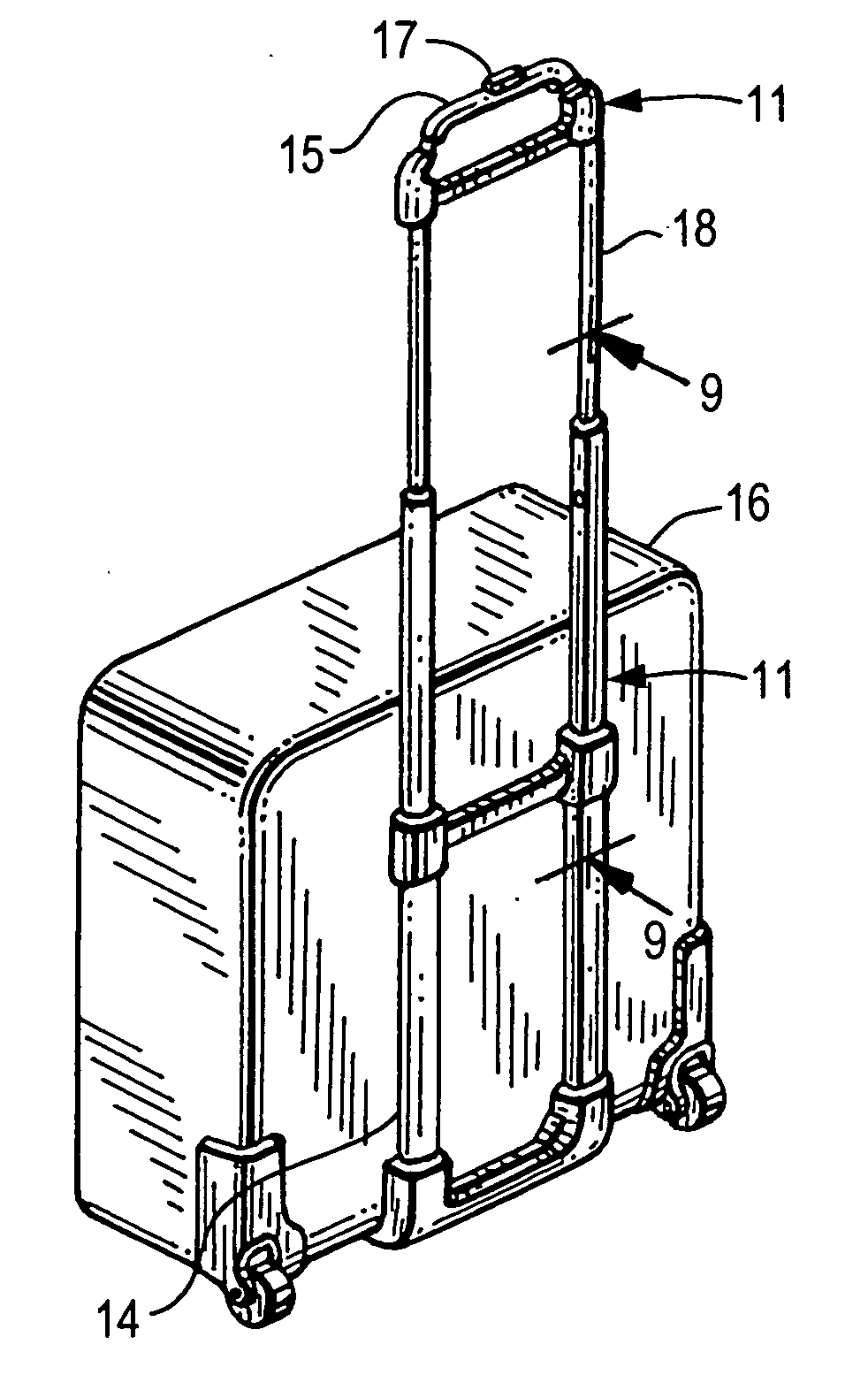
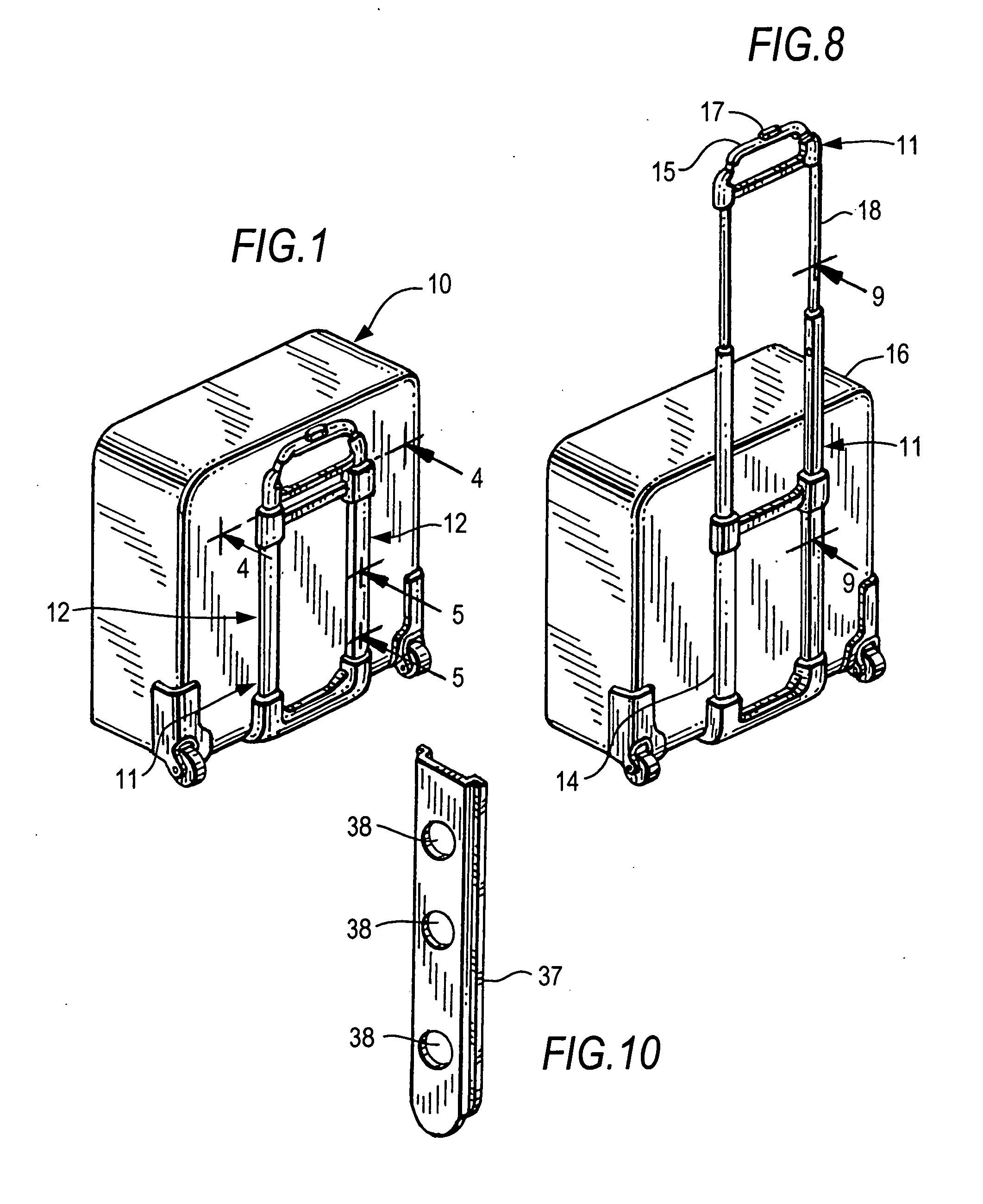
[0043]Referring initially to FIG. 1, there is shown a perspective view showing the handle of the present invention in its collapsed condition.

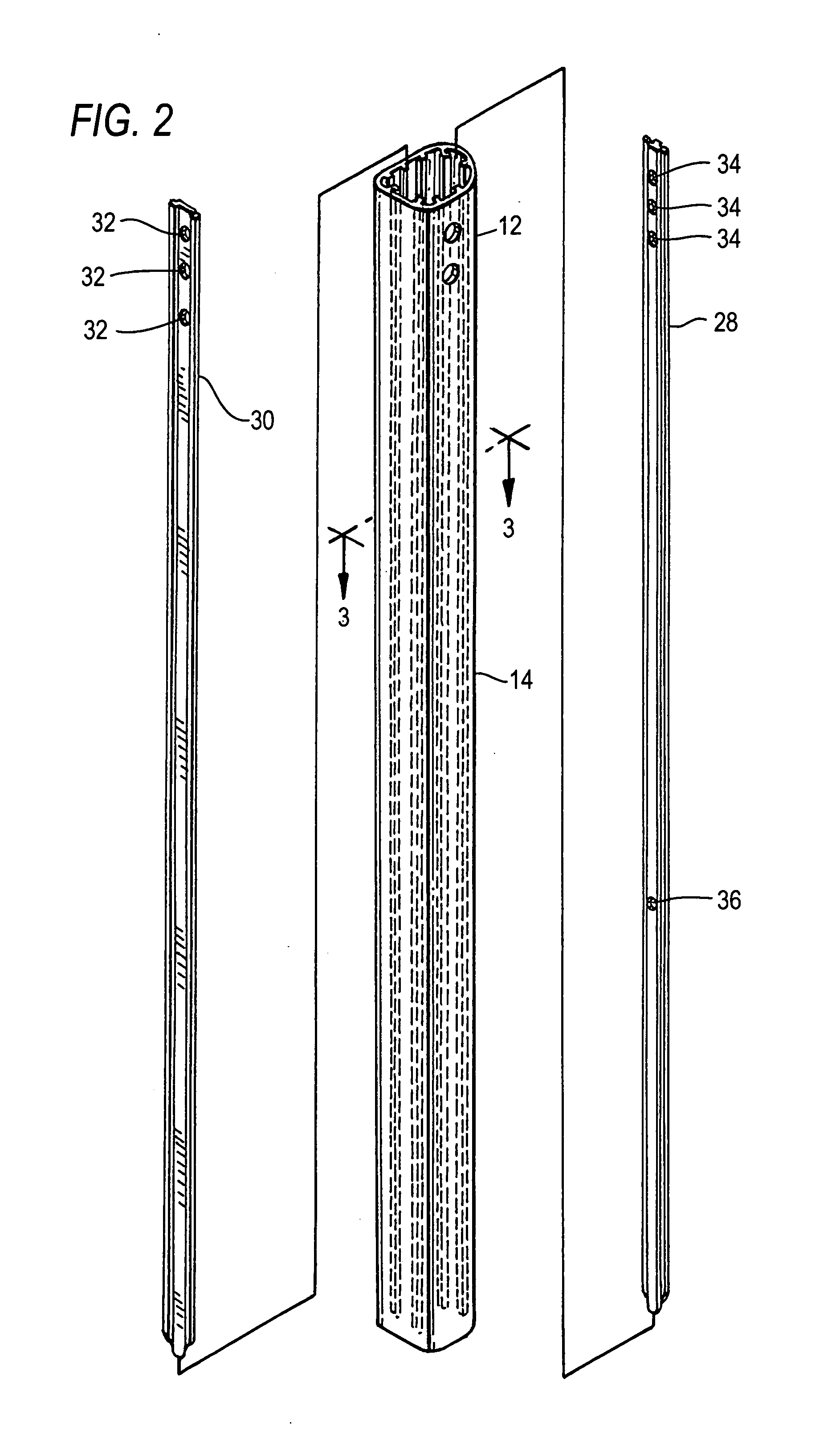
[0044]FIG. 2 shows an enlarged view of the first stage extruded plastic tube of the handle of FIG. 1, which retains two opposed metal strips which extend downwardly along each opposed inner side of the extruded plastic tube for added strength. Each metal strip has apertures for reception of locking pins which become aligned therewith. Moreover, the extruded plastic tube includes radially inwardly extending ribs for added strength.

[0045]FIG. 3 is an enlarged cross sectional view, taken along lines 3-3 of FIG. 2. This enlarged view shows the two metal strips in place, as well as the two telescopic handle second and third stage 16, 18 tubes in phantom. As the second and third stage aluminum tubes 16, 18 enter and exit the first stage tube 12, the second stage tube is guided by metal inserts 28, 30 as contact is made with the wear resistant surfac...


PUM


Abstract

Lightweight reinforced modular tubes of extruded plastic material are provided for the first stage of a trolley-type carry case, in combination with a locking mechanism, which facilitates effective extension and collapse of a multi-telescopic handle system. The tubes are made of extruded plastic material and include a pair of opposed metal strips having appropriately spaced and dimensioned apertures for reception of spring loaded locking pins of the telescopic system. The metal strips are respectively retained in position by a pair of radially extending elongated flange members which overlap marginal positions of the strips. The tubes and the metal strips can easily and quickly be cut to size to fit any size carry case. While the metal insert strips are preferably made of aluminum, any material stronger than the extruded plastic of the first stage tube can be used, i.e., steel, nylon, PVC, polyethylene, polycarbonate, or the like.

Description

CROSS-REFERENCE TO RELATED APPLICATIONS[0001]This application claims priority to U.S. Provisional Application No. 61 / 297,153, filed Jan. 21, 2010, the disclosure of which is incorporated herein by reference and made a part of this application.BACKGROUND OF THE INVENTION[0002]1. Field of the Invention[0003]The present invention relates to any lightweight reinforced extruded tubing for telescopic handles for trolley-type carry cases, wherein the first stage tube is reinforced by metal strips having apertures which are dimensioned and positioned to receive the spring biased locking pins of a multi-stage locking mechanism.[0004]2. Description of the Related Art[0005]Present day tube technology, particularly technology for the first (i.e., lowermost) stage of telescopic handles for carry cases has advanced in several stages. The following is a brief history of the developments of advancements in such tube technology.First Generation[0006]In general, the strength requirements of the pair ...

Claims


Application Information

Patent Timeline
Patent Type & Authority Applications(United States)
IPC IPC(8): A45C13/26A45C5/00
CPCY10T16/451A45C5/14A45C13/262
Inventor MOUSSATCHE, MICHEL H.CONTI, JOSEPHRADA, GEORGENEKRULIK, RICHARD J.CHUAN, WU-CHENCHANG, FU-KUEI
Owner BRIGGS & RILEY TRAVELWARE
Why Eureka
Try Eureka