
Variable geometry aircraft pylon structure and related operation techniques

a variable geometry, aircraft pylon technology, applied in the direction of machines/engines, aircraft navigation control, jet flaps, etc., can solve the problems of limiting the use of propulsive exhaust in swirling flow drag management applications, and limiting the use of propulsive exhaus

Inactive Publication Date: 2012-05-03
ATA ENG
View PDF0 Cites 21 Cited by
  • Summary
  • Abstract
  • Description
  • Claims
  • Application Information

AI Technical Summary

Benefits of technology

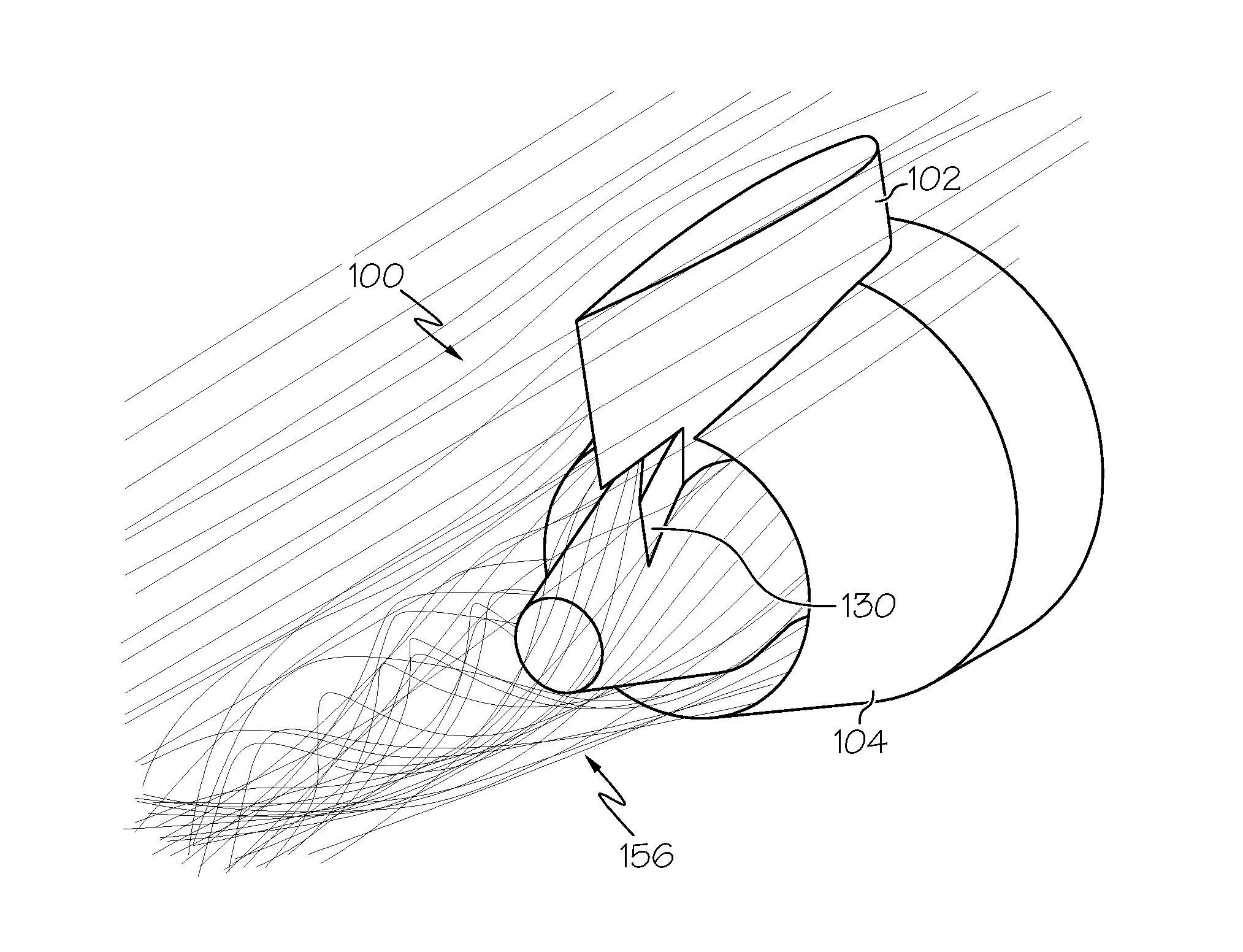
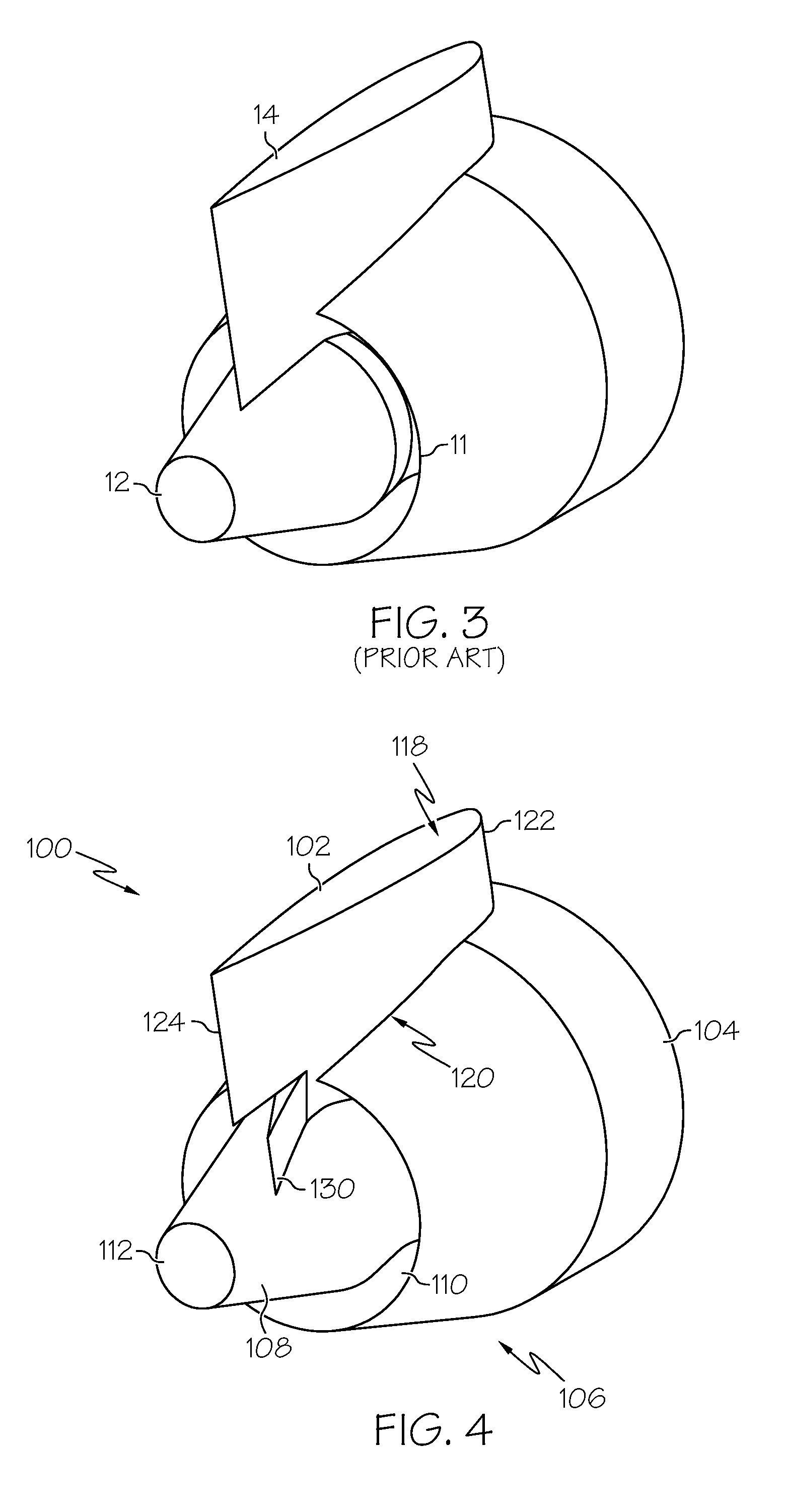
[0005]An exemplary embodiment of an aircraft control structure is provided. The aircraft control structure includes a nozzle assembly configured to exhaust a swirling fluid stream, and a pylon configured to be coupled between the nozzle assembly and an aircraft support structure. The pylon has a moveable pylon section positioned proximate an exit end of the nozzle assembly such that when deployed into a deflected state the moveable pylon section maintains the swirling fluid stream.
[0006]An exemplary embodiment of an aircraft subsystem is also provided. The subsystem includes a first engine configured to exhaust a first high pressure fluid stream, and a first variable geometry deployable pylon configured to be coupled between the first engine and an aircraft. The first variable geometry deployable pylon includes a first moveable pylon section positioned proximate an exit end of the first engine to influence a primary component of thrust of the first high pressure fluid stream. The subsystem also includes a control system to actuate the first moveable pylon section into a deflected state to redirect the first high pressure fluid stream and alter its primary component of thrust in accordance with a flight maneuver command for the aircraft.
[0007]Another embodiment of an aircraft subsystem is also provided. The subsystem includes a first nozzle and a first swirl vane assembly configured to exhaust a first swirling fluid stream, and a first variable geometry deployable pylon

Problems solved by technology

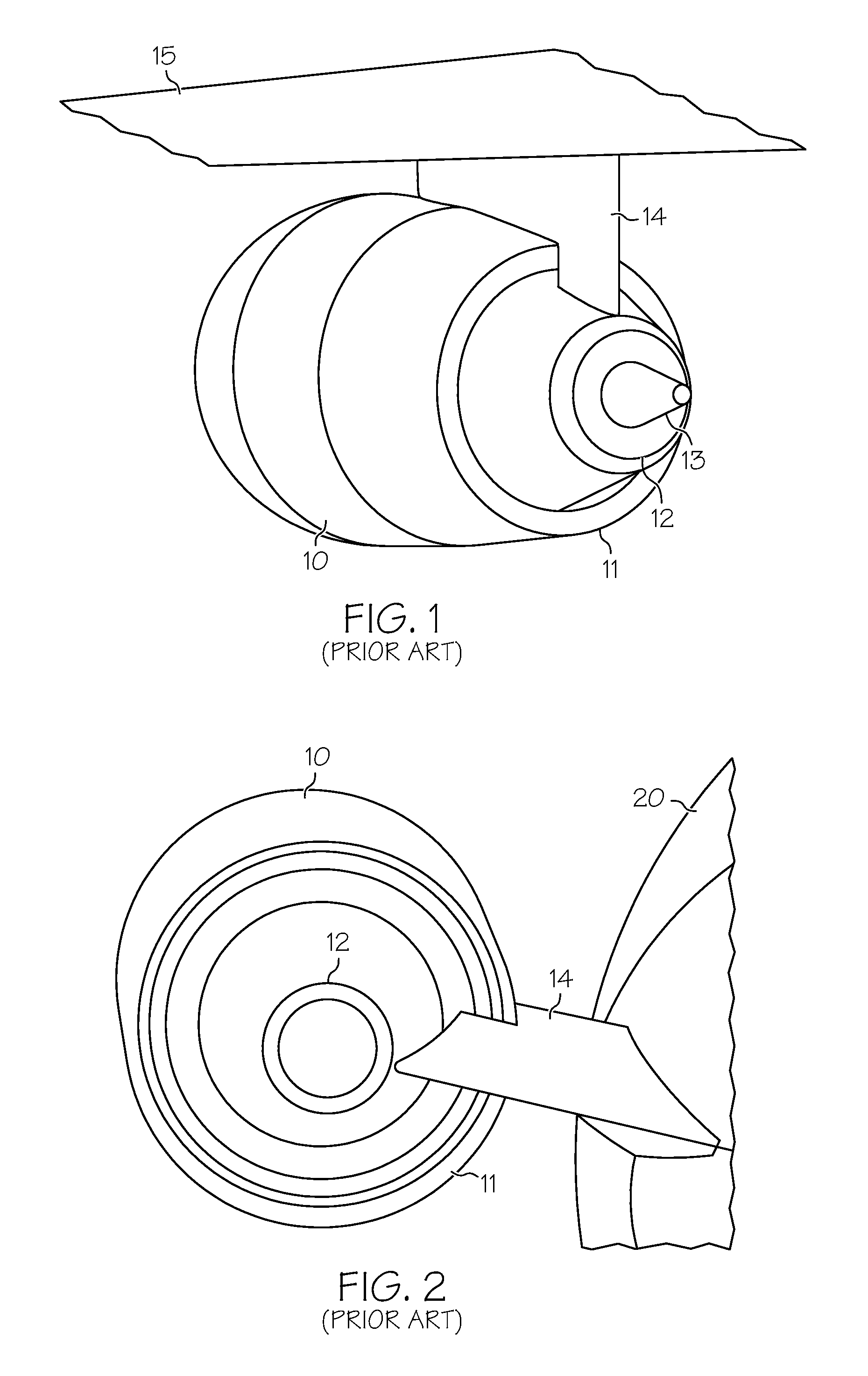
The presence of a pylon creates the need for an aerodynamic fairing cutting through a bypass flow stream, and limits the use of propulsive exhaust in swirling flows for drag management applications.
Additionally, pylons limit the use of propulsive exhaust in directing the flow for aircraft control purposes.

Method used


Image

  • Variable geometry aircraft pylon structure and related operation techniques
  • Variable geometry aircraft pylon structure and related operation techniques
  • Variable geometry aircraft pylon structure and related operation techniques

Examples


Embodiment Construction

[0025]The following detailed description is merely illustrative in nature and is not intended to limit the embodiments of the subject matter or the application and uses of such embodiments. As used herein, the word “exemplary” means “serving as an example, instance, or illustration.” Any implementation described herein as exemplary is not necessarily to be construed as preferred or advantageous over other implementations. Furthermore, there is no intention to be bound by any expressed or implied theory presented in the preceding technical field, background, brief summary or the following detailed description.

[0026]Techniques and technologies may be described herein in terms of functional and / or logical block components, and with reference to symbolic representations of operations, processing tasks, and functions that may be performed by various computing components or devices. Such operations, tasks, and functions are sometimes referred to as being computer-executed, computerized, s...


PUM


Abstract

An aircraft control structure can be utilized for purposes of drag management, noise control, or aircraft flight maneuvering. The control structure includes a high pressure engine nozzle, such as a bypass nozzle or a core nozzle of a turbofan engine. The nozzle exhausts a high pressure fluid stream, which can be swirled using a deployable swirl vane architecture. The control structure also includes a variable geometry pylon configured to be coupled between the nozzle and the aircraft. The variable geometry pylon has a moveable pylon section that can be deployed into a deflected state to maintain or alter a swirling fluid stream (when the swirl vane architecture is deployed) for drag management purposes, or to assist in the performance of aircraft flight maneuvers.

Description

CROSS-REFERENCE TO RELATED APPLICATION[0001]This application claims the benefit of U.S. provisional patent application Ser. No. 61 / 407,353, filed Oct. 27, 2010 (the entire content of which is incorporated by reference here).STATEMENT REGARDING FEDERALLY SPONSORED RESEARCH OR DEVELOPMENT[0002]The United States government has a paid-up license in this invention and the right in limited circumstances to require the patent owner to license others on reasonable terms as provided by the terms of contract number NNX09CA33C awarded by the National Aeronautics and Space Administration (NASA).TECHNICAL FIELD[0003]Embodiments of the subject matter described herein relate generally to aircraft structures and subsystems. More particularly, embodiments of the subject matter relate to an aircraft engine pylon structure having a variable geometry for drag management and flight control applications.BACKGROUND[0004]Turbofan engines require structural pylon hardware for mounting to the aircraft. Mount...

Claims


Application Information

Patent Timeline
IPC IPC(8): B64C15/02B64C9/38
CPCB64C7/02B64C9/36F02K1/383B64D33/04F02K1/12B64D27/18
Inventor SHAH, PARTHIV N.
Owner ATA ENG
Learn More