
Lighting power supply device and method for controlling holding current

Active Publication Date: 2012-05-03
MITSUMI ELECTRIC CO LTD
View PDF4 Cites 27 Cited by
  • Summary
  • Abstract
  • Description
  • Claims
  • Application Information

AI Technical Summary

Benefits of technology

[0009]The present invention is made in view of the above problems, and it is an object of the present invention to make a holding current suitable for a switching element of a phase control type dimmer flow in a lighting power supply device constituting a lighting system equipped with the phase control type dimmer, thus avoiding occurrence of malfunction without making any wasteful current flow.
[0010]Another object of the present invention is to enhance an electric power efficiency of the lighting power supply device constituting the lighting system equipped with the phase control type dimmer.

Problems solved by technology

On the other hand, in the power supply device for the LED lamp equipped with the phase control type dimmer, the LED lamp behaves like an inductive load, and therefore, when dimming is reduced, a current equal to or more than the holding current of the thyristor or triac does not flow, which may cause the phase control dimmer to malfunction.
For this reason, when a power supply device is designed to support all such phase control dimmers, current is wasted in a system using a dimmer which can operate with a holding current of several milliamperes, and there is a problem in that the electric power efficiency decreases.
However, the invention disclosed in Japanese Patent Application Laid-Open Publication No. 2009-158173 requires two power supply switch devices, i.e., the main power supply switch device and the sub-power supply switch device, and there is a problem in that the number of component parts increases, which makes it difficult to reduce the size of the dimmer.

Method used


Image

  • Lighting power supply device and method for controlling holding current
  • Lighting power supply device and method for controlling holding current
  • Lighting power supply device and method for controlling holding current

Examples


Embodiment Construction

[0024]Hereinafter, a preferred embodiment of the present invention will be described below with reference to the accompanying drawings.

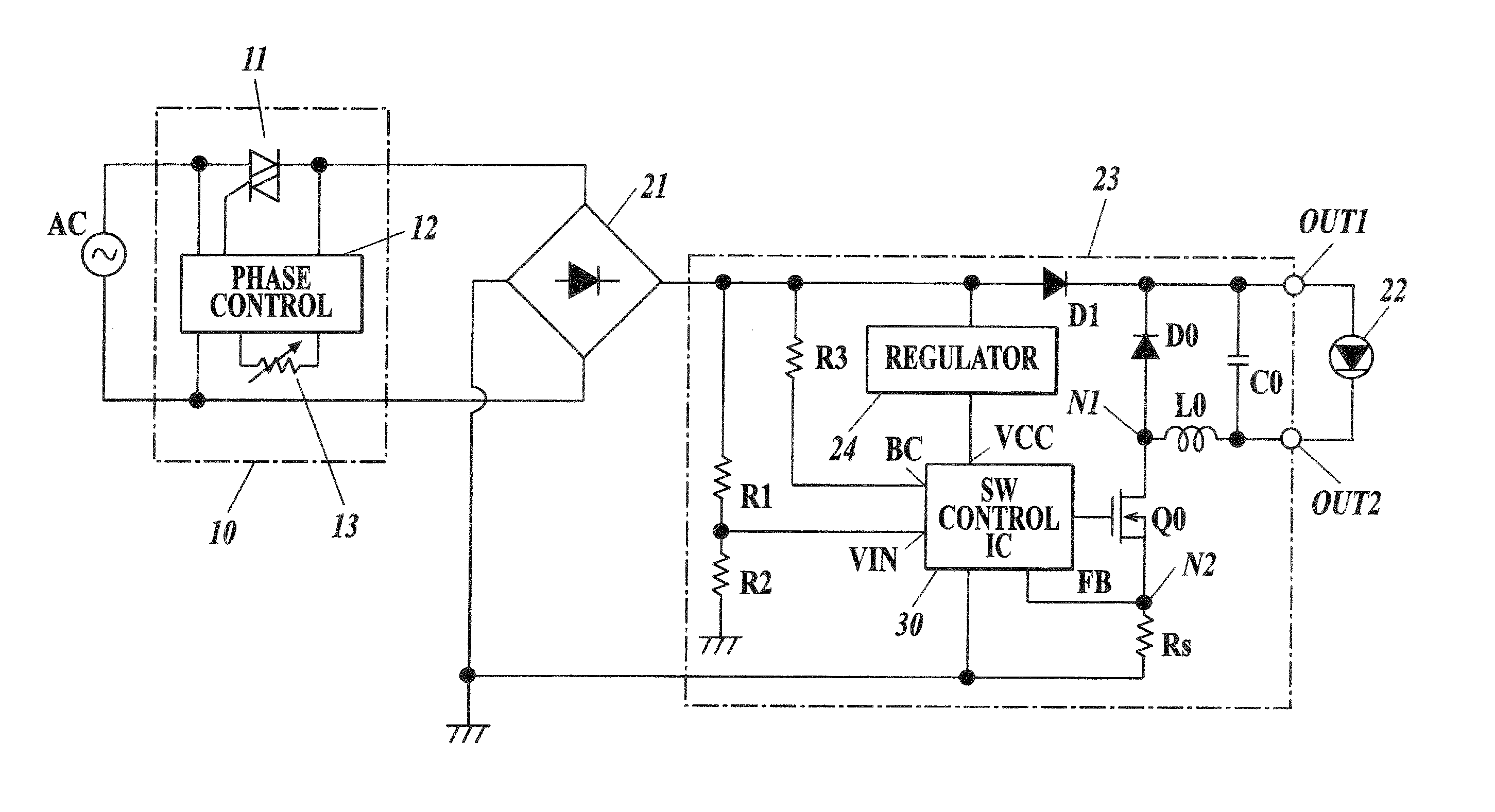
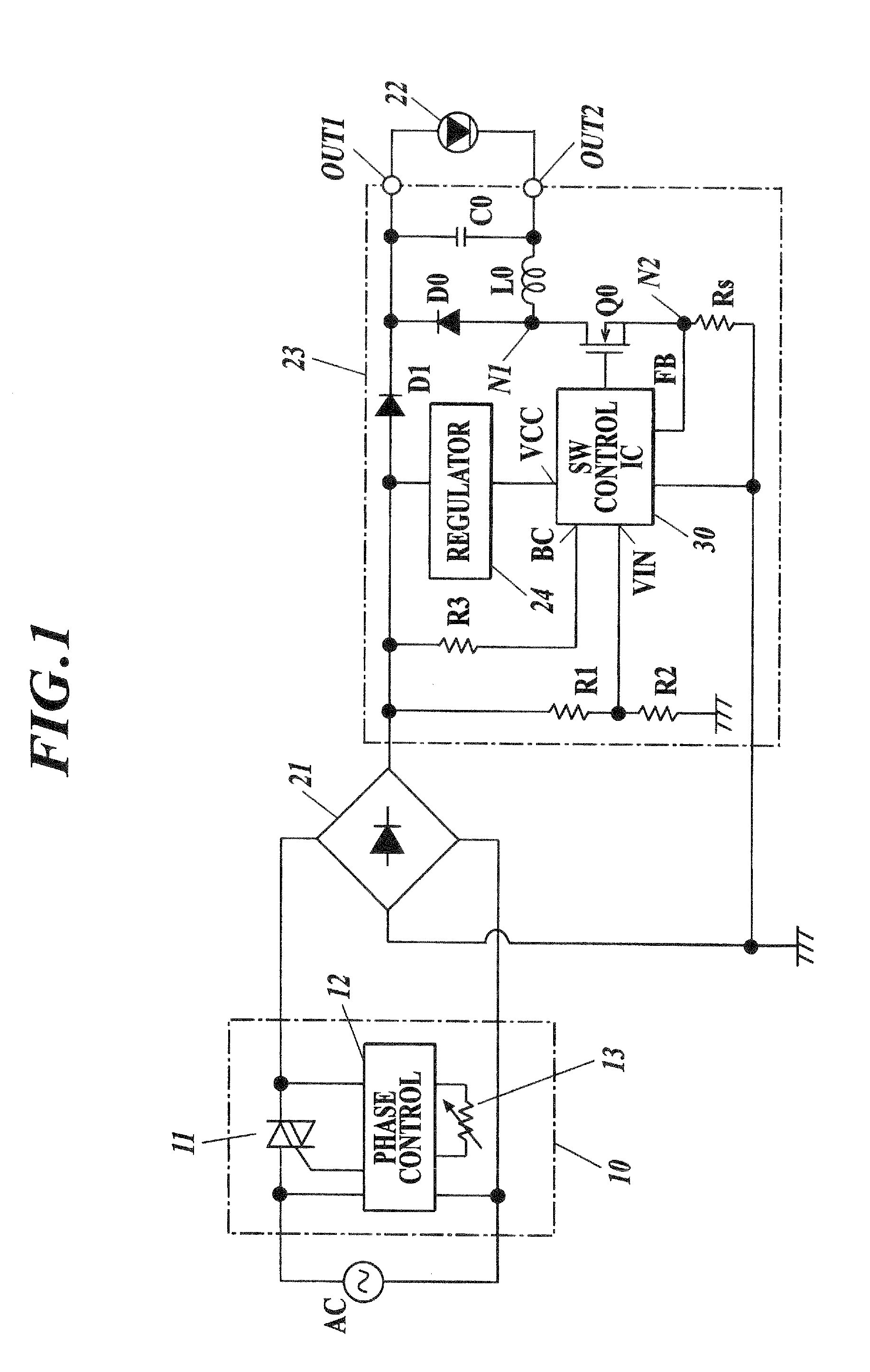
[0025]FIG. 1 shows a schematic configuration of a phase control type LED power supply device and an LED lighting system using the phase control type LED power supply device to which the present invention can be effectively applied.

[0026]As shown in FIG. 1, a phase control type LED lighting system according to the present embodiment includes: e.g., a phase control type dimmer 10 which receives an alternating-current power-supply voltage AC from a commercial alternating-current power supply and controls an ON phase angle of a switching element to change a duty ratio of the alternating-current power-supply voltage to output the alternating-current power-supply voltage; a rectifying circuit 21 which is composed of a diode bridge and the like and converts the input alternating current into a direct current through full-wave rectification; an LED power sup...


PUM


Abstract

A lighting power supply device receives a voltage converted from an alternating current to a direct current by a rectifying circuit rectifying the alternating current whose phase is controlled by a phase control type dimmer, and generates and outputs a direct current voltage / current to be supplied to a load. The lighting power supply device includes: a control circuit, and the control circuit gradually decreases a current drawn from the rectifying circuit from a predetermined current value set in advance, determines a current value immediately before detecting a malfunction of the phase control type dimmer as a drawn current value, and performs current control so as to maintain the determined current value.

Description

BACKGROUND OF THE INVENTION[0001]1. Field of the Invention[0002]The present invention relates to a lighting power supply device for performing dimming with a phase control type dimmer, and more particularly relates to a power supply device capable of controlling dimming of a lighting apparatus using a light emitting diode (LED) and a method for determining a holding current.[0003]2. Description of Related Art[0004]In recent years, a lighting device (hereinafter referred to as an LED lamp) using an LED consuming less electric power instead of an incandescent lamp consuming much electric power has been widely spread in order to reduce an amount of carbon dioxide emission. In the past, Japanese Patent Application Laid-Open Publication No. 2007-227155 has suggested a technique for controlling dimming with a phase control type dimmer in a power supply device for an LED lamp. Meanwhile, a dimming control has been performed with a phase control type dimmer also in a power supply device for...

Claims


Application Information

Patent Timeline
IPC IPC(8): H05B37/02H05B44/00
CPCH05B33/0887H05B45/50H05B45/3575H05B45/3725Y02B20/30H05B45/14H05B45/34
Inventor OKUBO, TAKASHIISOGAI, TARO
Owner MITSUMI ELECTRIC CO LTD
Learn More