Particle image velocimetry method, particle image velocimetry method for 3-dimensional space, particle image velocimetry system, and tracer particle generating device in particle image velocimetry system

a particle image velocimetry and particle image technology, applied in the field of particle image velocimetry, can solve the problems of reducing the s/n ratio of reflected light, reducing the measurement precision of flow velocity, and erroneous velocity vector calculation, so as to enhance the precision of measurement, enhance the accuracy of measurement of the state of flow, and reliably exclude erroneous vectors

Inactive Publication Date: 2012-05-03
HONDA MOTOR CO LTD
View PDF5 Cites 31 Cited by
  • Summary
  • Abstract
  • Description
  • Claims
  • Application Information

AI Technical Summary

Benefits of technology

[0040]In accordance with the first aspect of the present invention, tracer particles are supplied to the flow field around the object from the tracer particle supply means, images of reflected light are taken by the imaging means while irradiating the tracer particles with laser light twice at different times, and the velocity vector of the flow field is determined based on the two images obtained of the tracer particles. The two images are each divided into a plurality of test regions, and since the reliability of the velocity vector is determined by comparing a first peak value and a second peak value of the cross-correlation value of luminance patterns of the tracer particles in the respective test regions of the two images, it is possible to enhance the precision of measurement of the state of flow by reliably excluding erroneous vectors.
[0041]Furthermore, in accordance with the second aspect of the present invention, since it is determined that reliability of a velocity vector is high when first peak value / second peak value≧1.2 is satisfied, it is possible to enhance the precision of measurement of the state of flow by more reliably excluding erroneous vectors.
[0042]Moreover, in accordance with the third aspect of the present invention, the tracer particles contained in the flow field around:the object are irradiated with a two-dimensional laser sheet at two times that are spaced by a very small amount of time, images of the irradiated tracer particles are taken by the imaging means from two directions that intersect the laser sheet, when two in-plane velocity components of the tracer particles within the laser sheet and one out-of-plane velocity component perpendicular to the laser sheet are measured based on the images obtained at the two times, after three velocity components within a plurality of planes spaced in a direction perpendicular to the laser sheet are acquired, the three velocity components within the plurality of planes are stacked with the flow as a steady flow to thus measure the velocity field of the three velocity components in the three dimensional space, and it is therefore possible to measure three velocity components of the velocity field in the three dimensional space around the object.
[0043]Moreover, in accordance with the fourth aspect of the present invention, since the laser sheet irradiating means and the imaging means are supported on the moving member that is movable along the guide member disposed in a direction parallel to the laser beam forming the laser sheet, and the laser sheet irradiating means and the imaging means are moved while maintaining a fixed positional relationship, when the position of the laser sheet is moved in order to measure the velocity field of three velocity components in three dimensional space, it becomes unnecessary to carry out a different calibration each time, thereby reducing the number of calibration steps.
[0044]Moreover, in accordance with the fifth aspect of the present invention, since the laser head that emits a laser beam in a direction parallel to the direction of movement of the movement means is fixed to other than the movement means, and the laser sheet irradiating means converts the laser beam into a laser sheet, it becomes possible to move the position of the laser sheet without mounting the laser head on the movement means, thereby contributing to a reduction in the size of the movement means and a drive source therefor.
[0045]Furthermore, in accordance with the sixth aspect of the present invention, tracer particles contained in the flow field around the object are irradiated with laser light having a predetermined wavelength, an image of reflected light is taken by the imaging means, and the flow velocity of the flow field is determined based on the image obtained of the tracer particles. Since, at that time, the fluorescent surface of the object is excited by the laser light to thus generate fluorescence having a wavelength that is different from the wavelength of the laser light, by taking an image using a filter that allows only the wavelength of reflected laser light that has been reflected from the tracer particles to pass through, the S / N ratio of the image of the tracer particles can be enhanced, the influence of the light that has been reflected from the object is removed, and the precision of measurement of the flow velocity can be enhanced. Moreover, since it is unnecessary to impart fluorescent properties to the tracer particles, it is possible to prevent the ability of the tracer particles to follow the flow field from being degraded due to an increase in their weight and also prevent any adverse effects on the human body due to diffusion of tracer particles containing a harmful fluorescent material.

Problems solved by technology

In such a particle image velocimetry system, it is desirable to take an image of only light reflected from the tracer particles contained in the fluid, but in reality since it is inevitable that images of noise components such as halation, light reflected from an object placed in the fluid, and light reflected from dirt attached to an observation window of a wind tunnel are taken together with that of light reflected from the tracer particles, there is a possibility that, when the velocity vector of the fluid is calculated from the camera images, an erroneous velocity vector (erroneous vector) will be calculated.
Furthermore, when an image of tracer particles irradiated with the laser sheet is taken by imaging means, if an image of reflected light that has been reflected from an object as a background therefor is taken by the imaging means together with reflected light that has been reflected from the tracer particles, the reflected light from the object becomes noise to thus decrease the S / N ratio of the reflected light, thus causing the problem that the measurement precision for the flow velocity is degraded.

Method used


Image

  • Particle image velocimetry method, particle image velocimetry method for 3-dimensional space, particle image velocimetry system, and tracer particle generating device in particle image velocimetry system
  • Particle image velocimetry method, particle image velocimetry method for 3-dimensional space, particle image velocimetry system, and tracer particle generating device in particle image velocimetry system
  • Particle image velocimetry method, particle image velocimetry method for 3-dimensional space, particle image velocimetry system, and tracer particle generating device in particle image velocimetry system

Examples


first embodiment

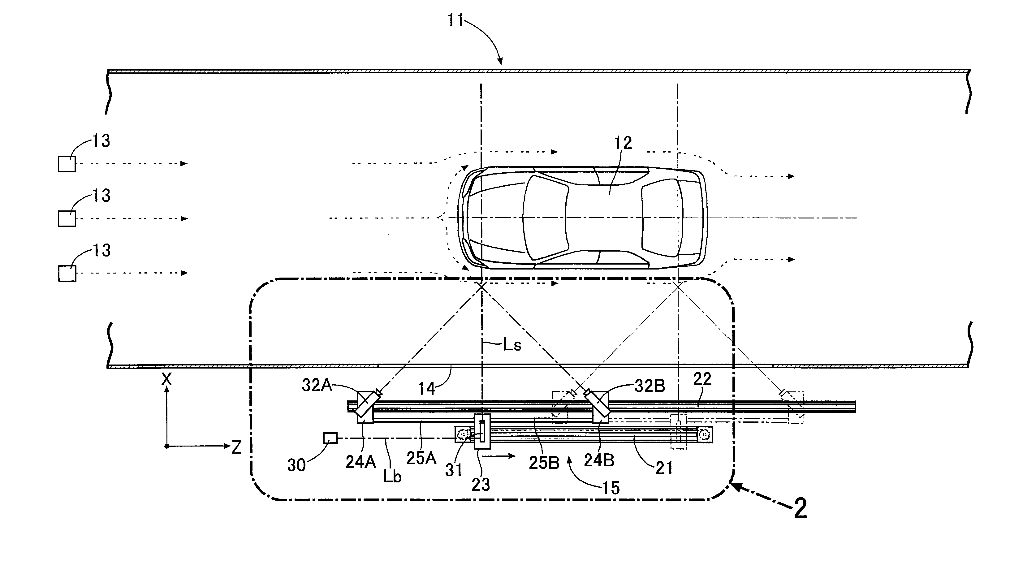
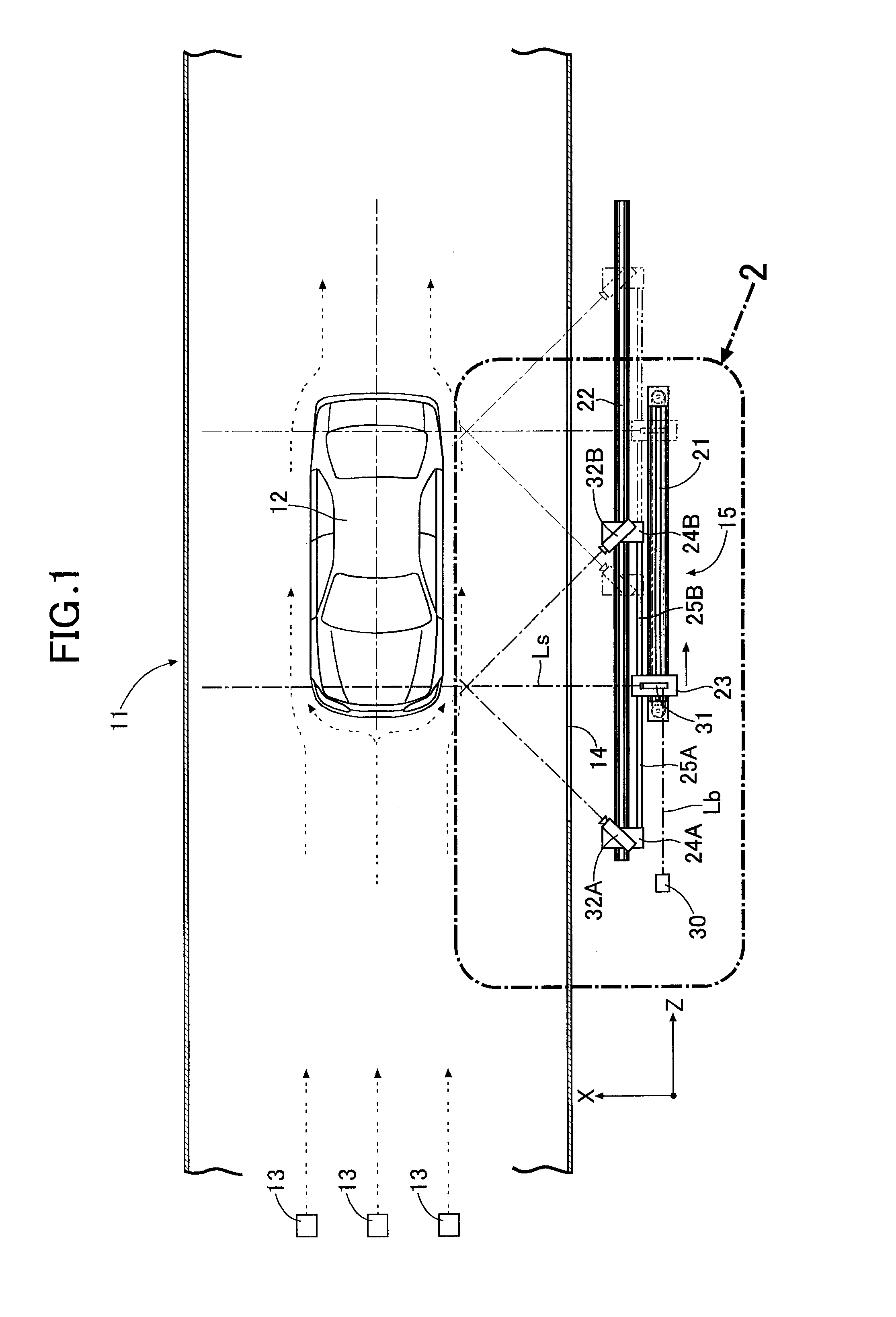
[0098]As shown in FIG. 1, an object 12 such as for example an automobile vehicle body model is placed in the interior of a wind tunnel 11 to which a uniform flow of air at a predetermined flow velocity is supplied, and fine oil droplets (tracer particles) having a diameter of a few μm are supplied into the uniform flow from tracer particle supply means 13 disposed on the upstream side of the object 12. The uniform flow changes its direction of flow along the surface of the object 12 and forms a three dimensional velocity field. A transparent observation window 14 is provided in at least part of a wall face of the wind tunnel 11, and a particle image velocimetry system 15 is disposed at a position facing the object 12 with the observation window 14 interposed therebetween.

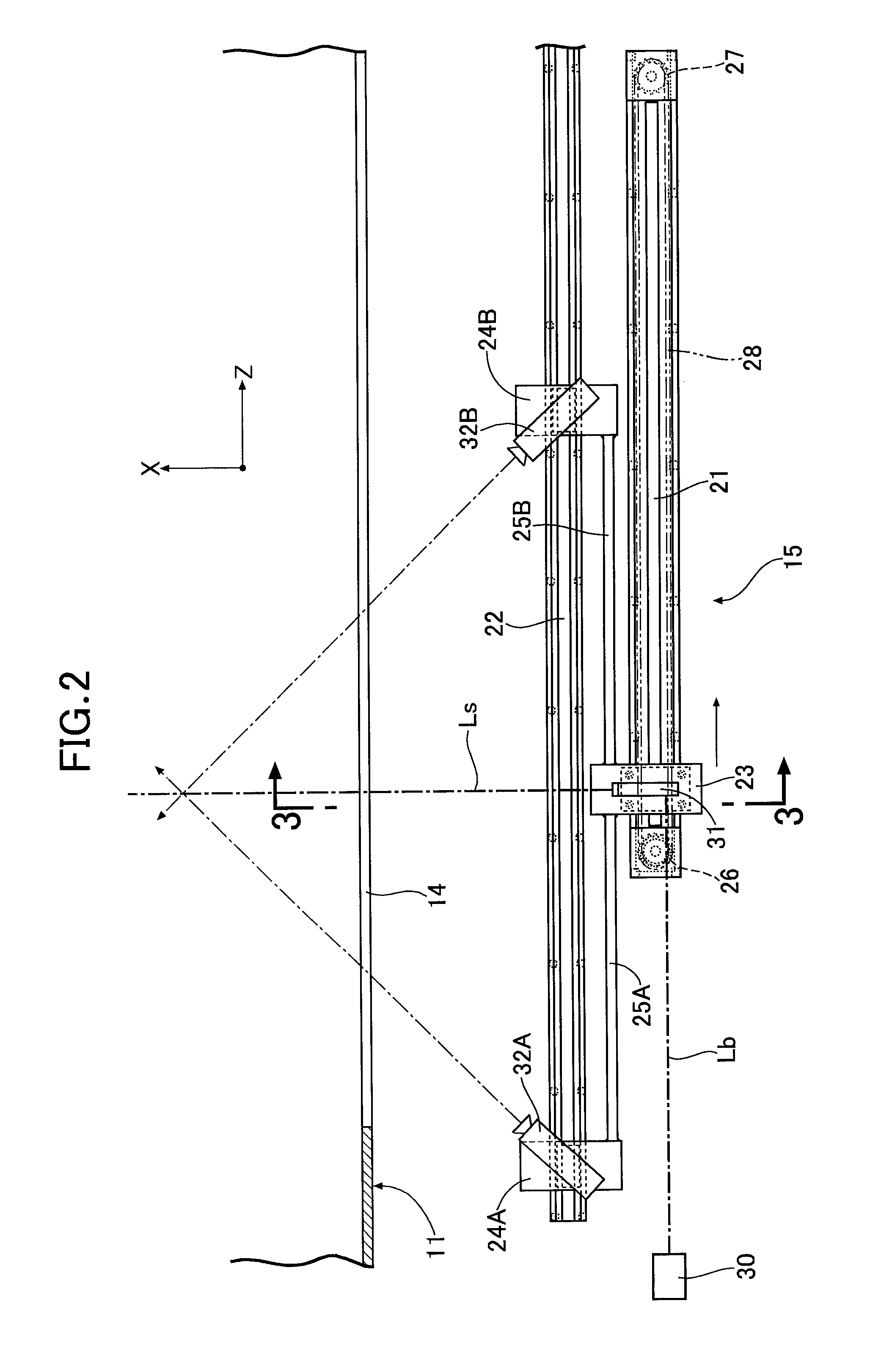
[0099]As shown in FIG. 2 to FIG. 4, the particle image velocimetry system 15 includes a main guide rail 21 disposed parallel to the axis of the wind tunnel 11, an auxiliary guide rail 22 disposed parallel to the mai...


PUM


Abstract

A particle image velocimetry system is provided which supplies tracer particles to a flow field around an object (12) from tracer particle supply means, takes an image of reflected light by imaging means (32A, 32B) by irradiating the tracer particles twice with laser light at different times, and determines a velocity vector of the flow field based on the two images obtained of the tracer particles. The two images are each divided into a plurality of test regions, and when first peak value (fp) / second peak value (sp)≧1.2 is satisfied by comparison between a first peak value fp and a second peak value sp of a cross-correlation value of a luminance pattern of tracer particles in each test region of the two images, it is determined that the reliability of the velocity vector is high. Thus, it is possible to enhance the precision of measurement of the state of flow by reliably determining erroneous vectors.

Description

[0001]The present invention relates to a particle image velocimetry method that involves supplying tracer particles to a flow field around an object from tracer particle supply means, taking an image of reflected light by imaging means by irradiating the tracer particles twice with laser light at different times, and determining a velocity vector of the flow field based on the two images obtained of the tracer particles.[0002]The present invention relates to a particle image velocimetry method for three dimensional space that involves irradiating tracer particles contained in a steady flow flowing around an object with a two-dimensional laser sheet at two times spaced by a very small period of time, taking an image of irradiated tracer particles by a camera from two directions that intersect the laser sheet, and measuring two in-plane velocity components of tracer particles within the laser sheet and one out-of-plane velocity component that is perpendicular to the laser sheet based ...

Claims


Application Information

Patent Timeline
Patent Type & Authority Applications(United States)
IPC IPC(8): H04N7/18
CPCG01M9/067G01P5/001G01P5/22G01P5/26G01S17/58
Inventor FUKUCHI, YUICHIYOSHINO, TAKASHITERAMURA, MINORUHOSHINO, GENSUKE
Owner HONDA MOTOR CO LTD
Why Eureka
Try Eureka