Vacuum kneading and deaerating device

a vacuum kneading and degasification technology, applied in the direction of liquid degasification, separation process, laboratory glassware, etc., can solve the problem that the kneading and degasification treatment already performed may possibly come to nothing, and achieve the effect of high efficiency, sufficient kneading and degasification, and sufficient kneading

Active Publication Date: 2012-05-03
MARUKOMU
View PDF12 Cites 10 Cited by
  • Summary
  • Abstract
  • Description
  • Claims
  • Application Information

AI Technical Summary

Benefits of technology

[0020]According to the vacuum kneading and deaerating device of the present invention, the paste container conducts orbital motion and precession at the same time under, for example, reduced pressure, thereby achieving sufficient kneading and deaerating actions on the paste material in the paste container fundamentally, so that the paste material in the paste container can be uniformly and sufficiently kneaded as a whole. In addition, the deaeration valve operated by the action of the centrifugal force, or the paste material-impermeable and gas-permeable membrane is provided in the opening portion of the paste container for placing the paste material, whereby the gas released in the internal space of the paste container by the deaerating action can be discharged out of the paste container to maintain the interior of the paste container at a proper degree of vacuum, so that the deaeration can be sufficiently conducted with a high efficiency, and the paste material after the treatment is provided as an even- and high-quality product.
[0021]Further, after the predetermined treatment is conducted, the paste container containing the paste material can be used in the present state as it is, so that the working efficiency can be improved, and it can be avoided to cause such an inconvenience that the quality of a final product using the paste material is lowered by mixing gas in the paste material again.

Problems solved by technology

However, since these paste materials are generally used in a state filled into, for example, a syringe, a possibility that when the paste material subjected to the kneading and deaerating treatment is transferred from the paste container to the syringe, a gas may be entrained therein comes to be increased, so that there is a problem that the kneading and deaerating treatment already performed may possibly come to nothing.

Method used


Image

  • Vacuum kneading and deaerating device
  • Vacuum kneading and deaerating device
  • Vacuum kneading and deaerating device

Examples


first embodiment

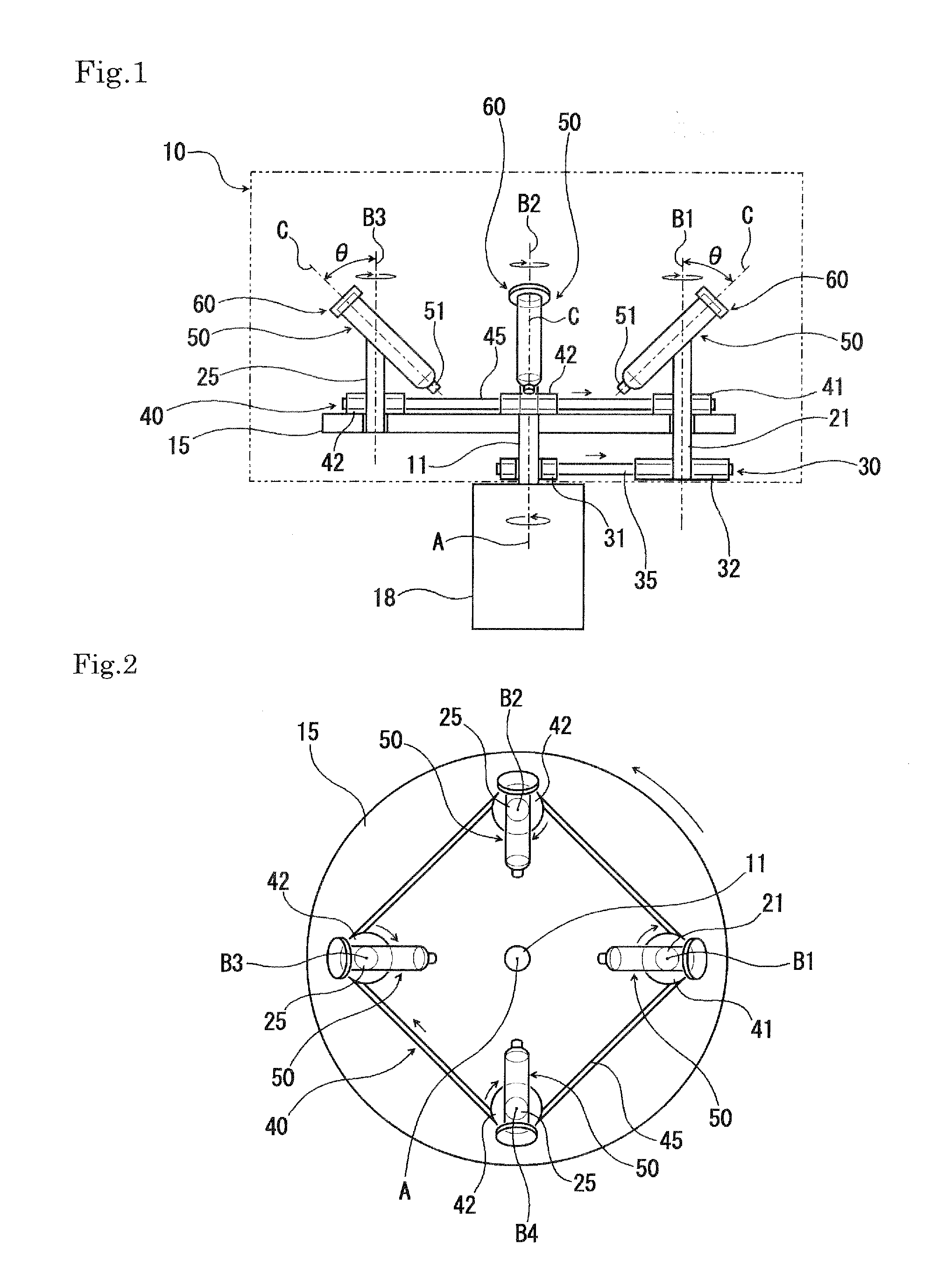
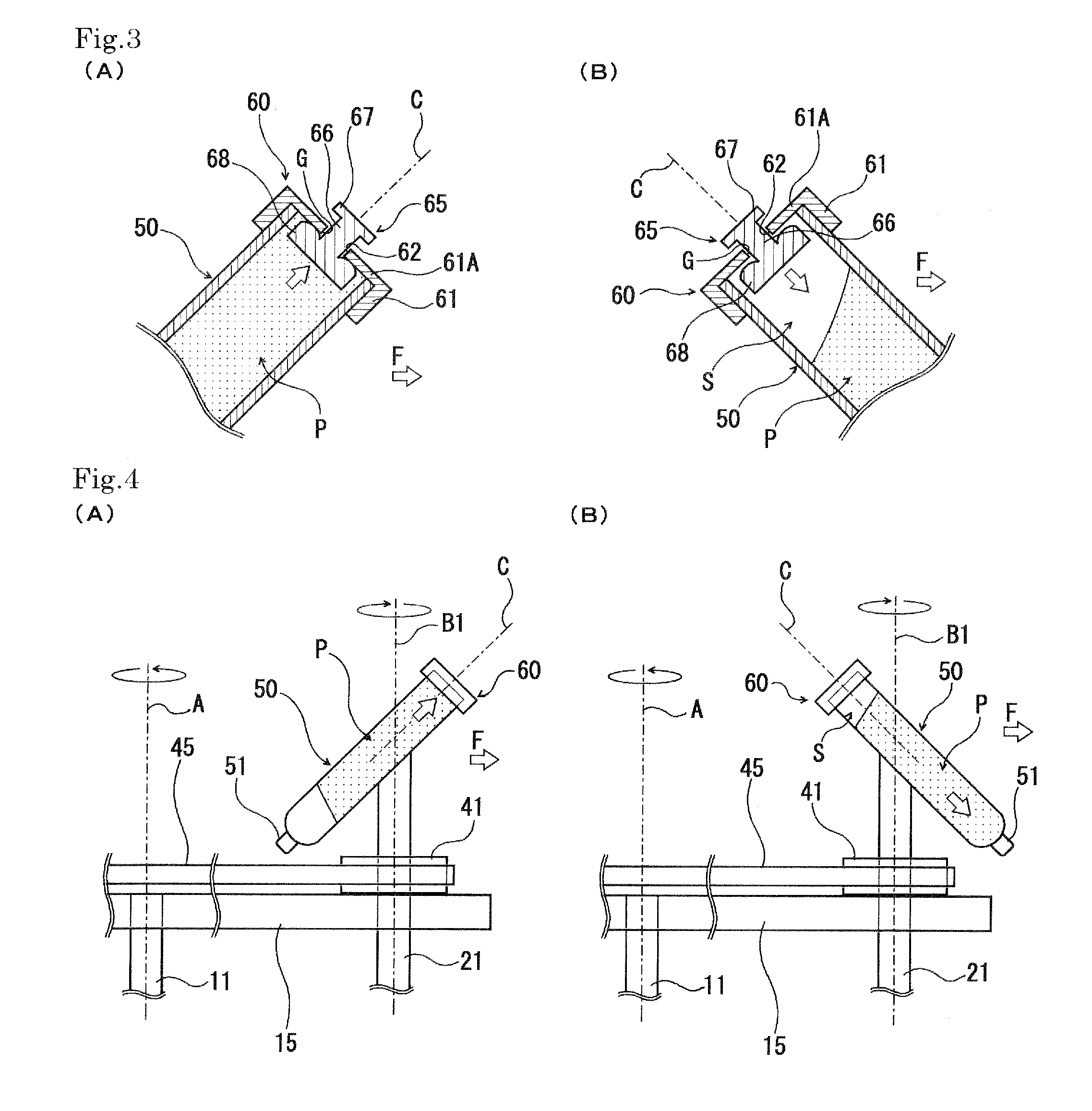
[0029]FIG. 1 is an explanatory sectional view schematically illustrating the fundamental construction of an exemplary vacuum kneading and deaerating device according to the first embodiment of the present invention, and FIG. 2 is a plan view of the vacuum kneading and deaerating device illustrated in FIG. viewed from the above in a vertical direction.

[0030]This vacuum kneading and deaerating device is equipped with a cylindrical chamber 10 forming a closed space in the interior thereof, a drive motor 18 having a driving rotation shaft 11 for revolution, which is rotationally driven on a central axis of rotation which is set as a basic driving rotation axis A, extending in a vertical direction, a disk-like rotating plate 15 for revolution, which is rotated in a horizontal plane on the basic driving rotation axis A, an operating rotation shaft 21 for rotation, which is provided rotationably on a central axis of rotation which is set as an operating rotation axis B1, extending in paral...

second embodiment

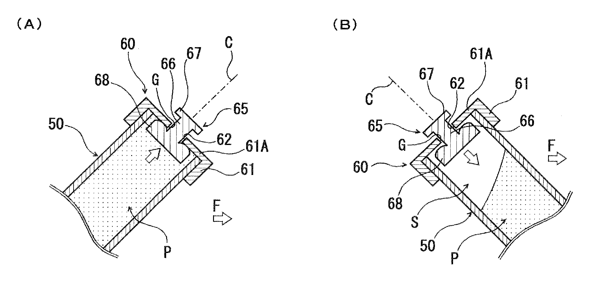
[0055]In a vacuum kneading and deaerating device according to the second embodiment of the present invention, a container of the construction that a lid member 70 having a degassing function is provided in an opening portion on one end side for placing the paste material P in the syringe-like container 50 is used as the syringe-like container 50.

[0056]As illustrated in FIG. 5(A) and FIG. 5(B), the lid member 70 is constructed by a cylindrical closed-end holder 61 detachably installed on the opening portion on one end side of the syringe-like container 50 so as to receive the one end portion of the syringe-like container 50 to close the opening portion of the syringe-like container 50 and a paste material-impermeable and gas-permeable membrane 75 provided on an inner surface of an end wall 61A of this holder 61 so as to cover a through-hole 62 formed in a central portion of the end wall 61A.

[0057]The gas-permeable membrane 75 is of, for example, a filmy form and can be formed by, for...


PUM

PropertyMeasurementUnit
pore sizeaaaaaaaaaa
pore sizeaaaaaaaaaa
pore sizeaaaaaaaaaa

Abstract

Disclosed is a vacuum kneading and deaerating device capable of conducting an uniform and sufficient kneading treatment and a sufficient deaerating treatment with a high efficiency for a paste material contained in a cylindrical paste container.
This vacuum kneading and deaerating device is equipped with a rotating body for revolution, which is provided in a chamber held under a closed or pressure-reduced condition and rotated in a horizontal plane around a basic driving rotation axis, a container holding means which is provided in the chamber rotationably on an operating rotation axis parallel to the basic driving rotation axis in a revolution edge portion of the rotating body for revolution and detachably holds a paste container in a state that a central axis of the paste container obliquely intersects the operating rotation axis, and a driving mechanism for rotating the rotating body for revolution and the container holding means, wherein a deaeration valve for opening an internal space of the paste container to an internal space of the chamber by the action of centrifugal force attending on the revolution and rotation of the paste container, or a paste material-impermeable and gas-permeable membrane is provided in an opening portion of the paste container for placing the paste material.

Description

TECHNICAL FIELD[0001]The present invention relates to a vacuum kneading and deaerating device.BACKGROUND ART[0002]For example, paste materials used as sealing compounds for liquid crystals, semiconductor elements, etc., conductive paste materials, resistor paste materials, or medical paste materials such as preparation pastes for ointments are required to be used in a state sufficiently kneaded and deaerated. Such a paste material is also often required to mix and disperse, for example, two or more liquids which are high in viscosity and different in specific gravity value, or a liquid and powder which are different in specific gravity.[0003]Devices of various types are proposed as a kneading and deaerating device for kneading and deaerating a paste material at present. For example, there is proposed a device of the construction that a container holder detachably holding, for example, a cup-like paste container, in which a paste material to be kneaded has been contained, is rotated ...

Claims


Application Information

Patent Timeline
Patent Type & Authority Applications(United States)
IPC IPC(8): B01F13/06B01F29/90
CPCB01D19/0026B01D19/0031B01D19/0047B01D19/0052B01F9/0001B01F9/0025B01F13/06B01L3/5021B01L3/50825B01L2400/06B29B7/106B29B7/845B01F29/10B01F29/331B01F33/70B01D19/00B01F29/90
Inventor HARADA, MANABU
Owner MARUKOMU
Why Eureka
Try Eureka