
Pre-reactor main shaft spiral system for hydrogen fluoride

A pre-reactor and hydrogen fluoride technology, which is applied in the direction of fluorine/hydrogen fluoride, etc., can solve the problems of insufficient reaction, easy material jamming, and material return, and achieve the effects of improving production efficiency and product quality, increasing stirring strokes, and improving service life

Active Publication Date: 2014-10-01
沈阳派司钛设备有限公司
View PDF4 Cites 2 Cited by
  • Summary
  • Abstract
  • Description
  • Claims
  • Application Information

AI Technical Summary

Problems solved by technology

Most of this equipment is relatively large, consumes a lot of energy, and the reaction yield and purity are not high.
In addition, this one-step reaction is very damaging to the furnace, resulting in a short life of the reactor
In order to solve this technical problem, the applicant applied for a Chinese utility model patent, the patent application number is 201120249083.X, and the name is "hydrogen fluoride pre-reactor". The main shaft system still has shortcomings, such as the screw system has a short stroke, poor mixing effect, insufficient reaction, easy to jam and return materials, and a large production load on the later equipment; it is difficult to transport the agglomerated materials during the reaction, and the system is easy to be blocked. , causing mechanical failure, the equipment is difficult to operate continuously, resulting in a large amount of CuF and sulfuric acid residues, and large environmental pollution; it is made of a variety of materials, and cracks are prone to occur in welding between different materials, and the welding method is unreasonable and even directly leads to equipment in operation. The phenomenon of tearing and detachment at the welding seam of the blade appears; the reaction liquid at the spiral joint surface has serious erosion and corrosion on the acid feeding port

Method used


Image

  • Pre-reactor main shaft spiral system for hydrogen fluoride
  • Pre-reactor main shaft spiral system for hydrogen fluoride

Examples


Embodiment Construction

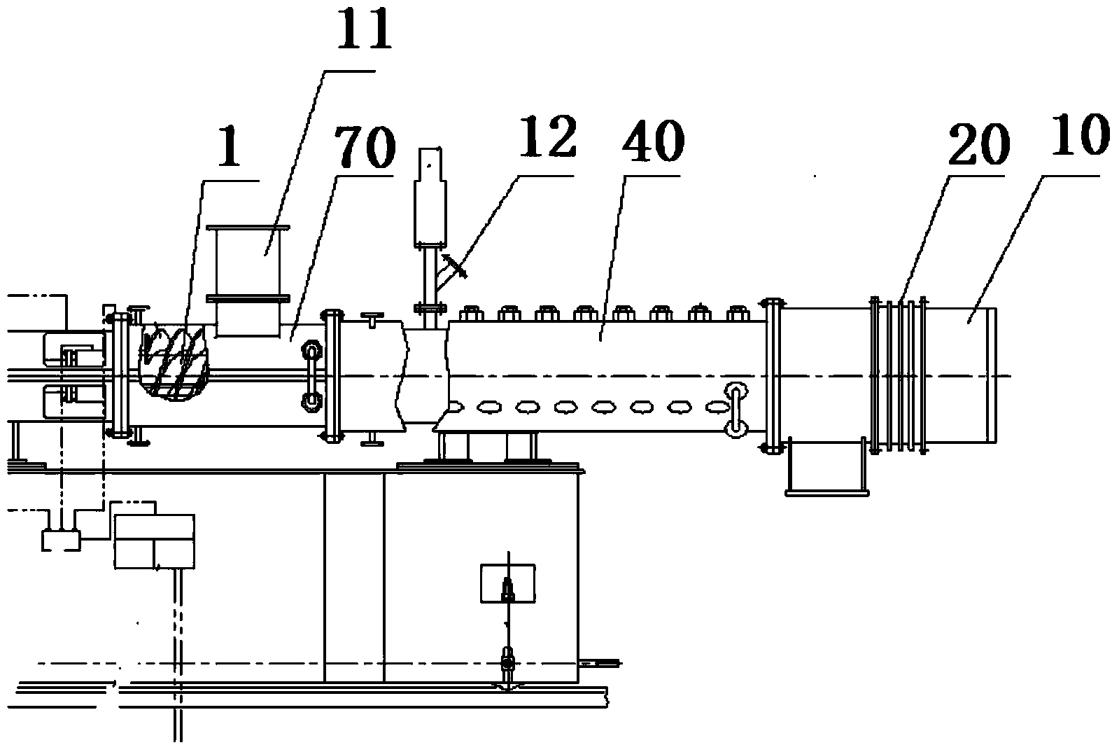
[0017] The present invention is specifically described below in conjunction with accompanying drawing, as Figure 1-Figure 2 As shown, the present invention is applied to the equipment disclosed in Chinese Patent Application No. 201120249083.X, named "hydrogen fluoride pre-reactor", which comprises an extension section 10, an extension section compensator 20, a main reaction section 40, a feeding Section 70, screw spindle 1, etc.; feeding section 70 is provided with fluorite feeding port 11 and acid feeding port 12; hydrogen fluoride pre-reactor spindle screw system, including main shaft 1, stuffing box sleeve 2, fluorite feeding section paddle 3. The reaction section paddle 4, the extension section shaft 5, the extension section paddle 6, the reaction section shaft sleeve 7, the fluorite feeding section shaft sleeve 8, the bearing bush 9, and the fluorite feeding section paddle 3 is welded on On the shaft sleeve 8 of the fluorite feeding section, the paddle 4 of the reaction ...


PUM


Abstract

The invention discloses a pre-reactor main shaft spiral system for hydrogen fluoride. Fluorite charging section blades are welded on a fluorite charging section shaft sleeve; reaction section blades are welded on a reaction section shaft sleeve; extension section blades are welded on an extension section shaft; the length is greater than 5 meters; the extension section blades, fluorite charging section blades and reaction section blades are respectively welded with a stellite alloy in an overlay welding mode; the pitch between the reaction section blades and the blades at the acidification port is increased; a 130-145mm-long spiral short section is added to the tail end of the main shaft, so that the acidification port deviates from the spiral junction surface by 180-200mm; the fluorite charging section blades and fluorite charging section shaft sleeve are made of the same material; and the reaction section blades and reaction section shaft sleeve are made of the same material; and the extension section blades and the extension section shaft are made of the same material. The system has the advantages of sufficient reaction, no blocking, no material return, favorable abrasion resistance, low failure rate, long equipment life and high yield, and is suitable for delivering slurry and lumping materials as well as high-abrasion materials.

Description

technical field [0001] The invention relates to the field of chemical industry, in particular to a spindle system of a pre-reactor for hydrogen fluoride. Background technique [0002] The existing hydrofluoric acid production usually adopts a one-step process, that is, the fluorite and sulfuric acid are simply mixed in a reactor and reacted directly. Most of these devices are bulky, consume high energy, and have low reaction yield and purity. In addition, this one-step reaction is very damaging to the furnace, resulting in a short life of the reactor. In order to solve this technical problem, the applicant applied for a Chinese utility model patent, the patent application number is 201120249083.X, and the name is "hydrogen fluoride pre-reactor". The main shaft system still has shortcomings, such as the screw system has a short stroke, poor mixing effect, insufficient reaction, easy to jam and return materials, and a large production load on the later equipment; it is diffi...

Claims


Application Information

Patent Timeline
IPC IPC(8): C01B7/19
Inventor 林英肖明坤王琛
Owner 沈阳派司钛设备有限公司
Learn More