Anti-rotation shroud for turbine engines

Active Publication Date: 2012-05-03
GENERAL ELECTRIC CO
View PDF7 Cites 20 Cited by
  • Summary
  • Abstract
  • Description
  • Claims
  • Application Information

AI Technical Summary

Benefits of technology

[0005]The present disclosure describes embodiments of an improved shroud for turbine engines with 180 degree split turbine casings. The shroud has an integrated anti-rotation device that prevents circumferential movement of the shroud during normal engine operation, and which allows for circumferential installation. Since the anti-rotation device is an integral part of the shroud, no additional parts are necessary for assembly or disassembly. Moreover, existing turbine cases can be reworked to accept the anti-rotation device and yet still be backwards compatible with original shroud designs.

Problems solved by technology

However, this anti-rotation device is an extra part that must be installed, disassembled and / or maintained in addition to other components of the turbine engine.

Method used


Image

  • Anti-rotation shroud for turbine engines
  • Anti-rotation shroud for turbine engines
  • Anti-rotation shroud for turbine engines

Examples


Embodiment Construction

[0026]As used herein, an element or function recited in the singular and proceeded with the word “a” or “an” should be understood as not excluding plural said elements or functions, unless such exclusion is explicitly recited. Furthermore, references to “one embodiment” of the claimed invention should not be interpreted as excluding the existence of additional embodiments that also incorporate the recited features.

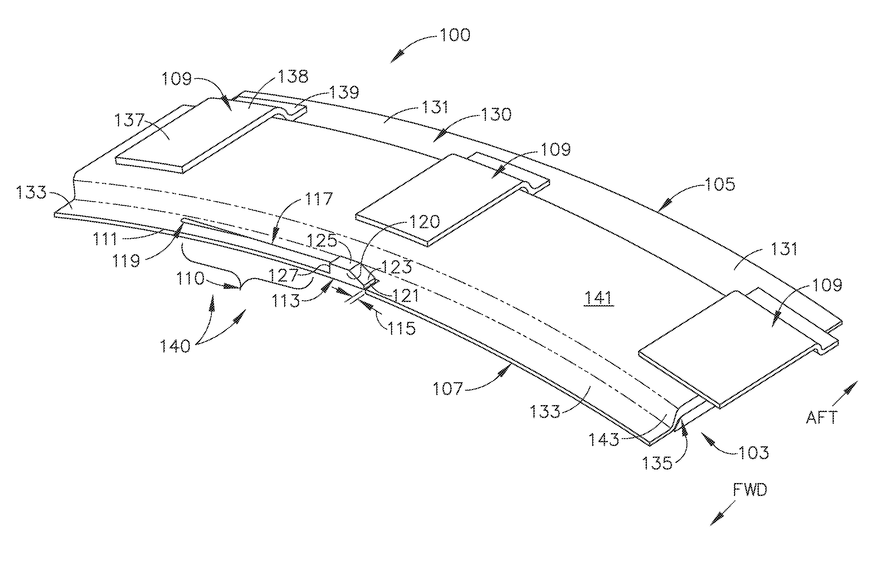
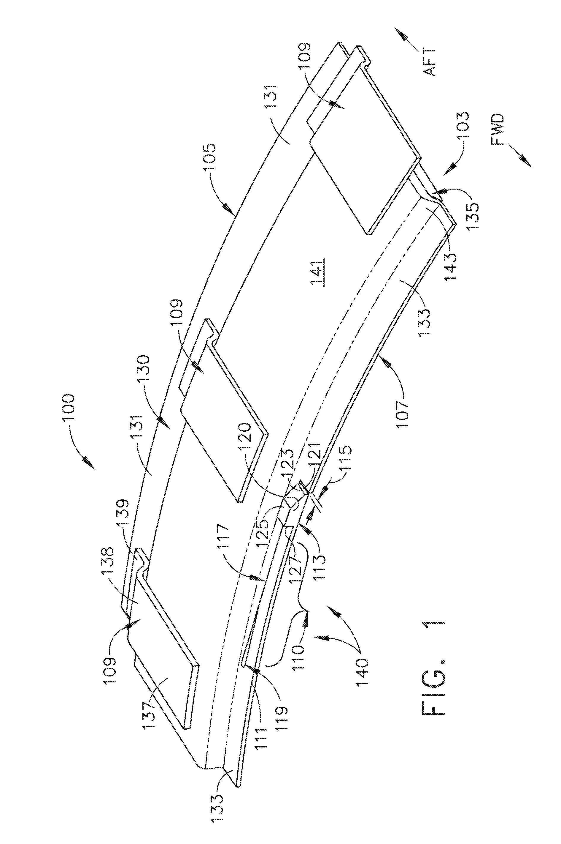
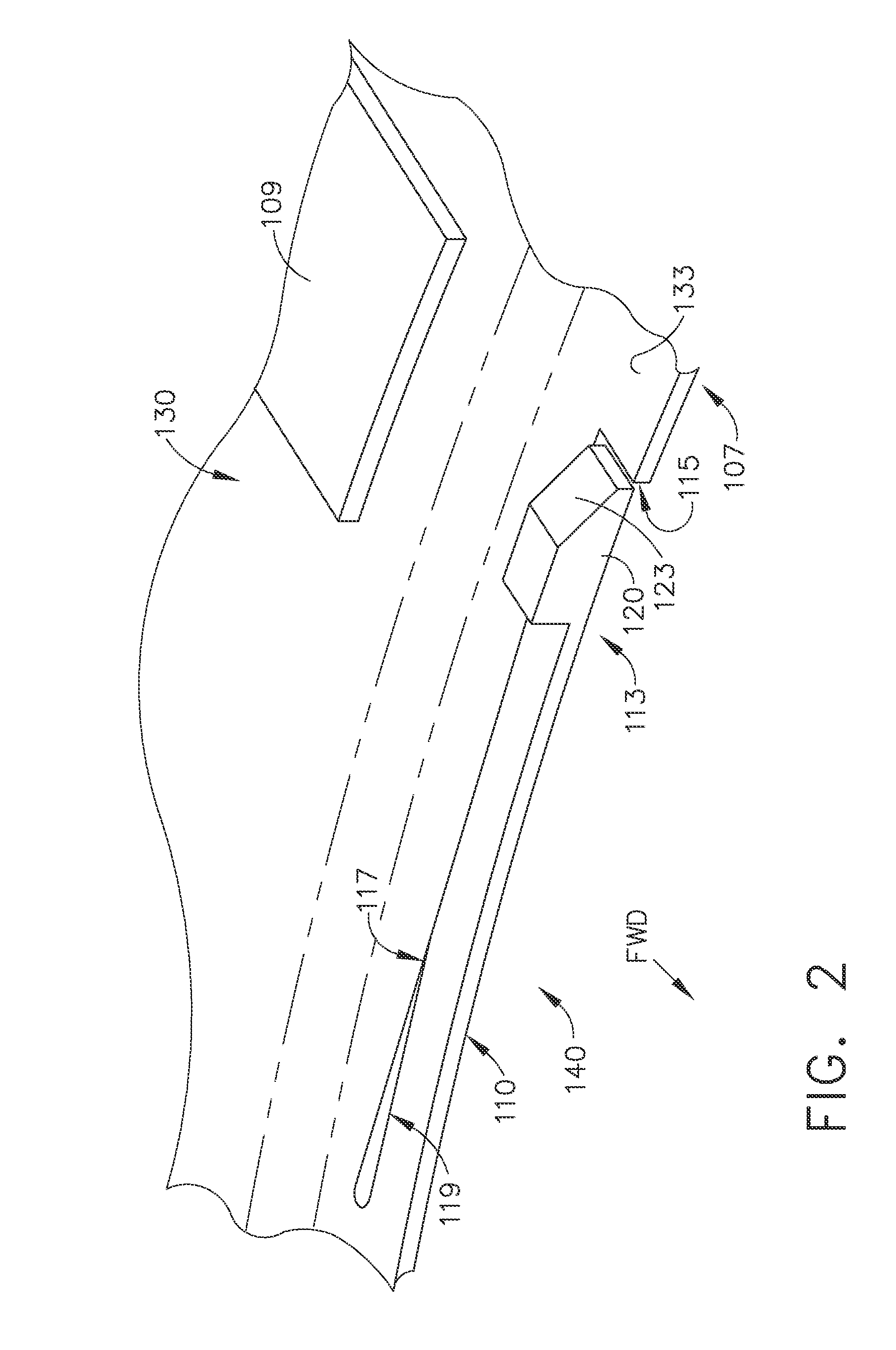
[0027]FIG. 1 is a perspective view of a portion of an improved turbine shroud 100 configured for use in a turbine engine. FIG. 2 is a partial, close-up view of an anti-rotation device 140 integrally formed with the improved turbine shroud 100 of FIG. 1. FIG. 3 is another partial, close-up view of the anti-rotation device 140 of FIG. 2. FIG. 4 is a plan view illustrating an interior surface 142 of the improved turbine shroud 100 of FIG. 1. FIG. 4A is an end view of the improved turbine shroud 100 of FIGS. 1 and 4. FIG. 4B is a forward side view of the improved turbine shrou...


PUM


Abstract

A shroud for turbine engines. The shroud has an integrated anti-rotation device that prevents circumferential movement of the shroud during normal engine operation, and which allows for circumferential installation in split annular case designs. Since the anti-rotation device is an integral part of the shroud and/or annular split turbine case, no additional parts are necessary for assembly or disassembly. Moreover, existing annular split turbine cases can be reworked to accept the anti-rotation device and yet still be backwards compatible with original shroud designs.

Description

BACKGROUND OF THE INVENTION[0001]1. Field of the Invention[0002]The field of the invention relates to turbine engines generally, and more particularly to certain new and useful advances in anti-rotation features for turbine shrouds, of which the following is a specification, reference being had to the drawings accompanying and forming a part of the same.[0003]2. Description of Related Art[0004]Turbine engines comprise an airfoil attached to a rotor that rotates about a predetermined axis of rotation. An annular shroud is circumferentially positioned about and spaced apart from the airfoil. An annular split turbine case is circumferentially positioned about and coupled with the shroud. Additionally, an anti-rotation device is added and coupled with the shroud to prevent the shroud from rotating during normal engine operations. However, this anti-rotation device is an extra part that must be installed, disassembled and / or maintained in addition to other components of the turbine engin...

Claims


Application Information

Patent Timeline
Patent Type & Authority Applications(United States)
IPC IPC(8): F04D29/42
CPCF01D11/001F01D25/24Y02T50/672F05D2240/11F05D2240/14F01D25/28F01D25/246F01D11/08F01D11/003F05D2260/30F05D2260/36Y02T50/60
Inventor CHAN, GEORGE JOE-KUENGCORREIA, VICTOR HUGO SILVA
Owner GENERAL ELECTRIC CO
Why Eureka
Try Eureka