
Traction Method And System For An Operating Line, In Particular A Mooring Line, Of A Floating Production Unit

a technology of operating line and mooring line, which is applied in the direction of floating buildings, waterborne vessels, etc., can solve the problems of cable damage, hazardous situations, and system more or less similar to the one described, and achieve the effects of simple, reliable, and safe operation of operating lines

Inactive Publication Date: 2012-05-10
SAIPEM SPA
View PDF22 Cites 6 Cited by
  • Summary
  • Abstract
  • Description
  • Claims
  • Application Information

AI Technical Summary

Benefits of technology

The present invention provides a safer, easier, and more reliable method and system for tensioning operating lines, particularly mooring lines, of a floating production unit. The invention prevents damage to the line and hazardous situations during tensioning, even when using a simple and low-cost winch. The main cable socket engages the sheave with very little pull on the cable, allowing the first chain link to come into contact with the sheave in the correct position. Connecting the main cable directly to the operating line eliminates the need for auxiliary chain portions and reduces the work and equipment required for handling them.

Problems solved by technology

Normally, the end of the cable that attaches to the chain portions is defined by a cast head, known as a socket, which, as it runs through the sheave, tends to irreparably damage the cable.
A second drawback involves the orientation of the first link (of any chain portion) as it comes into contact with the sheave.
Since it is practically impossible to ensure the first link of the incoming chain is in the ideal position to engage the sheave, and given also the amount of pull exerted by the cable when the chain reaches deck level, due to twisting of the cable, extremely hazardous situations may arise.
Systems more or less similar to the one described also pose the same problems.

Method used


Image

  • Traction Method And System For An Operating Line, In Particular A Mooring Line, Of A Floating Production Unit
  • Traction Method And System For An Operating Line, In Particular A Mooring Line, Of A Floating Production Unit
  • Traction Method And System For An Operating Line, In Particular A Mooring Line, Of A Floating Production Unit

Examples


Embodiment Construction

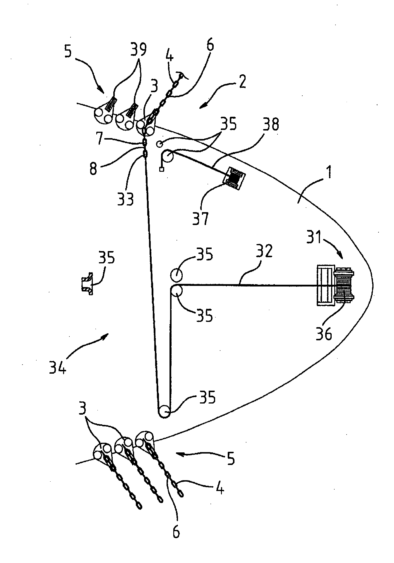
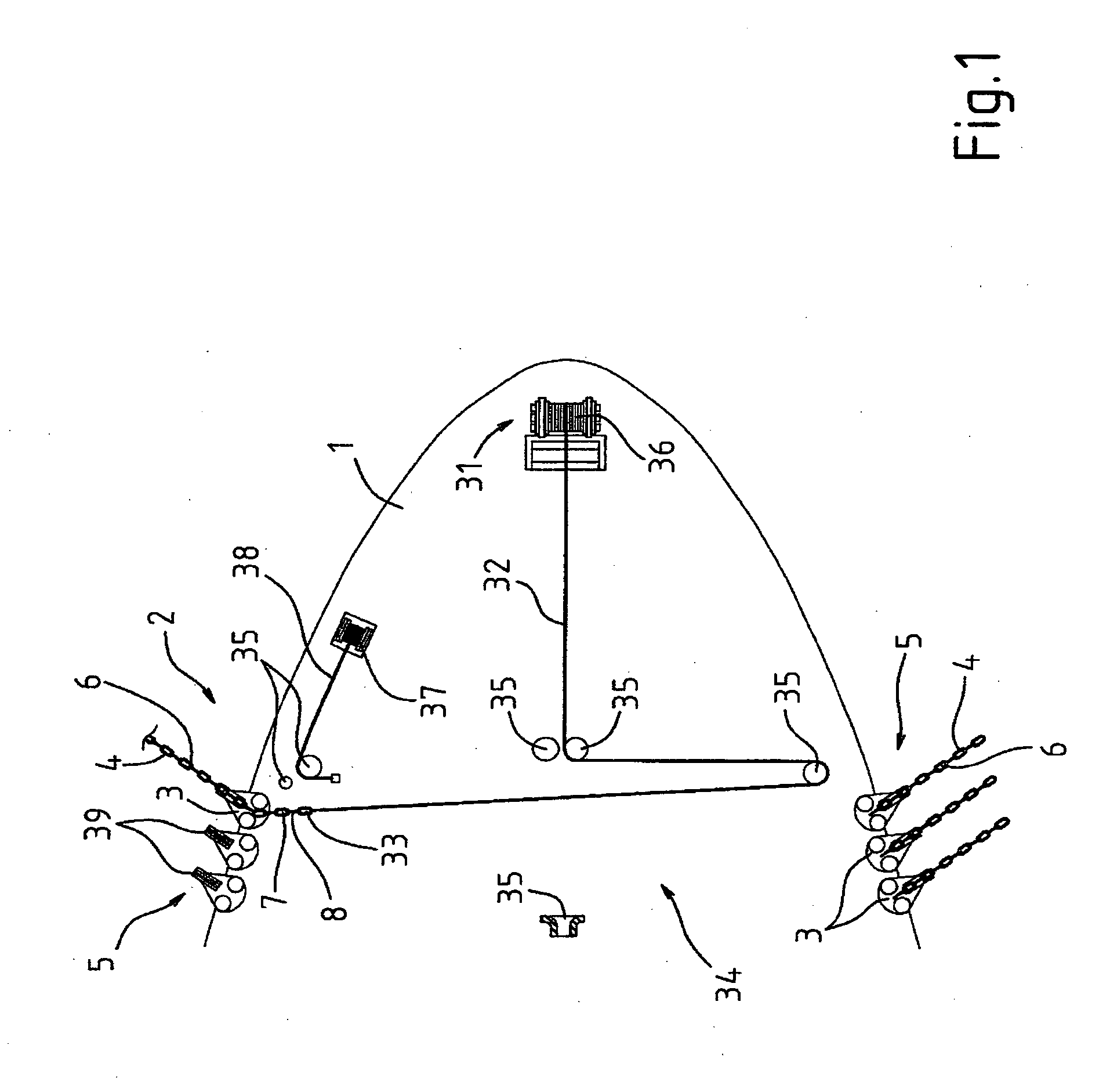
[0022]Number 1 in FIG. 1 indicates a floating production unit, e.g. of the type commonly known as an FPSO and defined by a converted ship, only shown partly and schematically for the sake of simplicity.

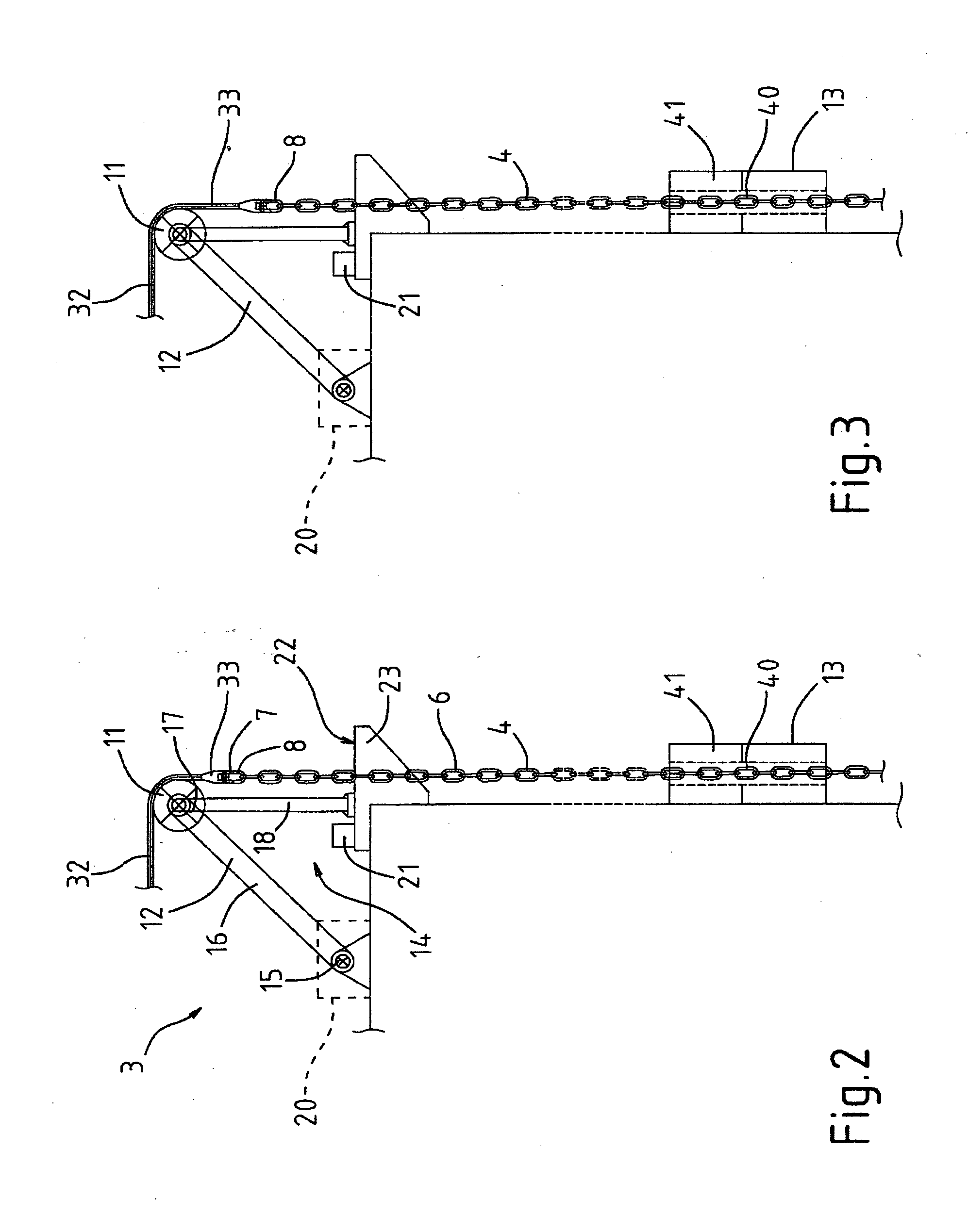
[0023]Unit 1 comprises an operating line traction system 2, in turn comprising at least one work station 3, in particular a mooring station, which cooperates with an operating line 4, in particular a mooring line.

[0024]In the non-limiting FIG. 1 embodiment, unit 1 has a number of work stations 3 spaced along unit 1 and engaged by respective operating lines 4. More specifically, stations 3 comprise a number of mooring stations arranged along unit 1, optionally in groups 5 to form a spread mooring configuration, and engaged by respective mooring lines; and possibly also a number of production stations engaged by respective known hydrocarbon extraction lines, not shown for the sake of simplicity.

[0025]It is understood that stations 3 may be arranged differently on unit 1, and also in moo...


PUM


Abstract

A traction method for an operating line, in particular a mooring line, of a floating production unit includes the steps of: attaching an end chain portion of the operating line to a socket of a main cable running through a sheave at a work station; reeling in the main cable, using a winch, to bring the socket of the main cable up to the sheave; locking the operating line with a chain stopper; slackening the main cable and moving the sheave closer to the chain stopper to reduce pull on the main cable; reeling in the main cable to run the socket of the main cable through the sheave; once the socket of the main cable has run through the sheave, releasing the operating line from the chain stopper, and reeling in, by means of the winch, the main cable and the operating line connected to it, to set the operating line to a given tension.

Description

TECHNICAL FIELD[0001]The present invention relates to traction method and system for an operating line, in particular a mooring line, of a floating production unit, and to a floating production unit featuring such a system.[0002]The method according to the invention is particularly suitable for “spread mooring” floating production units, to which application the following description refers purely by way of example.BACKGROUND ART[0003]As is known, floating production units (FPUs) and, specifically, floating production, storage and offloading (FPSO) vessels, widely used for off-shore hydrocarbon production, are normally converted ships anchored permanently by mooring lines to the sea bed.[0004]A mooring line normally comprises a first chain portion, which is fixed to a mooring station on the unit by a locking device; a cable portion (e.g. of synthetic material); and a second chain portion terminating with an anchor.[0005]Normally, there are several mooring lines attached to respectiv...

Claims


Application Information

Patent Timeline
Patent Type & Authority Applications(United States)
IPC IPC(8): B63B21/16B63B35/44
CPCB63B21/16B63B21/04
Inventor FENINI, ALESSANDROGAMBA, GIANFRANCO
Owner SAIPEM SPA
Learn More