View port device for plasma process and process observation device of plasma apparatus

a plasma process and view port technology, applied in the direction of chemical vapor deposition coating, coating, electric discharge tube, etc., can solve the problems of complex honeycomb structure shutter used in the said generally known technology, high cost, decay and distortion of light radiated by the active reaction species inside the reaction chamber, etc., to achieve simple structure and manufacturing method of the view port device for the plasma process, the effect of low cos

Inactive Publication Date: 2012-05-10
IND TECH RES INST
View PDF7 Cites 3 Cited by
  • Summary
  • Abstract
  • Description
  • Claims
  • Application Information

AI Technical Summary

Benefits of technology

[0010]The disclosure is directed to a view port device for a plasma process and a process observation device of a plasma apparatus. The structure and manufacturing method for the view port device for a plasma process are simple and incur low cost, and the process observation device of a plasma apparatus can be formed with simple elements. The process observation device with a view port device reduces the amount of the active reaction deposition species being diffused to the view port glass from the reaction chamber during the plasma or the etching process, so that the level or rate at which the view port glass is polluted is low, and the view port glass still maintain excellent optical transmission during a long duration of reaction process.

Problems solved by technology

The film deposited on the view port glass would deteriorate the optical transmission of the view port glass and thus make the light radiated by the active reaction species inside the reaction chamber decay.
As the process time increase, the decay and distortion would get worse.
However, the honeycomb structure shutter used in the said generally known technology is complicated and incurs high cost, and also requires the use of additional devices such as vacuum pipes, valves, and sealing device.
Besides, the introduced gas flow may affect the stability in the current field inside the reaction chamber.

Method used


Image

  • View port device for plasma process and process observation device of plasma apparatus
  • View port device for plasma process and process observation device of plasma apparatus
  • View port device for plasma process and process observation device of plasma apparatus

Examples


first embodiment

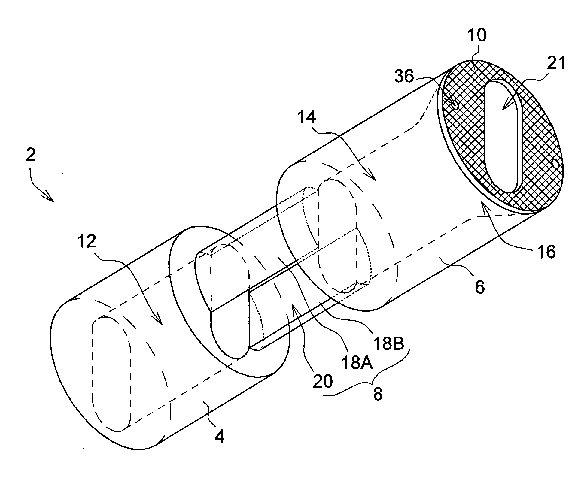
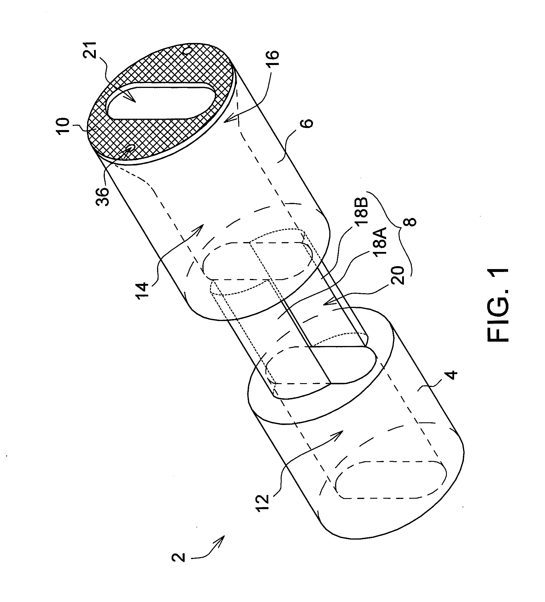
[0022]FIG. 1 shows a 3-D perspective of a view port device of a Referring to FIG. 1, the view port device 2 comprises a first substrate portion 4, a second substrate portion 6, a connecting portion 8 and a mesh element 10. The first substrate portion 4 has a first through hole 12. The second substrate portion 6 has a second through hole 14 and a second diffusion space 16. The mesh element 10 has an observation hole 21, and can be formed by a metal such as stainless mesh, aluminum mesh or titanium mesh. The mesh element 10 can be fixed on the second substrate portion 6 through a fixing pin 36. However, the invention is not limited thereto. In other embodiments, for example, the mesh element 10 can be embedded into the second substrate portion 6. The connecting portion 8 may comprise third substrate portions 18A and 18B and an opening 20 which is disposed between the third substrate portions 18A and 18B. However, the connecting portion 8 is not limited to the structure exemplified ab...

second embodiment

[0028]FIG. 5 shows an enlargement view of a plasma apparatus of a The plasma apparatus of FIG. 5 is different from the plasma apparatus of FIG. 3 in that the first diffusion space 65 is formed between the opening 63 of the connecting portion 62 of the view port device 61 and the chamber wall 64 of the plasma apparatus. The cross-sectional area of the first diffusion space 65 is larger than that of the first through hole 66 and is larger than that of the second through hole 67. The first through hole 66, the second through hole 67, the first diffusion space 65 and the second diffusion space 68 are interconnected to form an observation path.

third embodiment

[0029]FIG. 6 shows a 3-D perspective of a view port device of a The view port device 40 of FIG. 6 is different from the view port device 2 of FIG. 1 in that the first substrate portion 48, the second substrate portion 52 and the connecting portion 42 are an integral one-piece structure, and the connecting portion 42 has a first diffusion space 46 therein. The cross-sectional area of the first diffusion space 46 is larger than that of the first through hole 50 of the first substrate portion 48 and is larger than that of the second through hole 54 of the second substrate portion 52. The first substrate portion 48, the second substrate portion 52 and the connecting portion 42 can be an integral one-piece structure. The structure and manufacturing method for view port device 40 are simple and incur low cost.

[0030]In embodiments of the invention, the structure and manufacturing method for the view port device are simple and incur low cost, and the process observation device of a plasma ...


PUM

PropertyMeasurementUnit
angleaaaaaaaaaa
spectrum wavelengthaaaaaaaaaa

Abstract

A view port device for a plasma process and a process observation device of a plasma apparatus are provided. The view port device for a plasma process comprises a first substrate portion, a second substrate portion, and a connecting portion. The first substrate portion has a first through hole. The second substrate portion has a second through hole and a second diffusion space. A cross-sectional area of the second diffusion space is larger than that of the second through hole. The connecting portion is disposed between the first substrate portion and the second substrate portion.

Description

[0001]This application claims the benefit of Taiwan application Serial No. 99138209, filed Nov. 5, 2010, the subject matter of which is incorporated herein by reference.BACKGROUND[0002]1. Technical Field[0003]The invention relates in general to a view port device, and more particularly to a plasma process observation device with a view port device.[0004]2. Description of the Related Art[0005]A plasma enhanced chemical vapor deposition process can be used for depositing and etching a film. A result of the depositing and etching the film is closely related to a concentration of active reaction species during the process. Therefore, it is very important to observe and analyze the change in the concentration among the active reaction species during the plasma process.[0006]For example, a method for observing the plasma enhanced chemical vapor deposition process is using an optical emission spectroscopy (OES) for capturing the plasma spectral changes of the active reaction species inside...

Claims


Application Information

Patent Timeline
Patent Type & Authority Applications(United States)
IPC IPC(8): B05C11/00
CPCC23C16/50H01J37/32935H01J37/32798
Inventor DU, CHEN-CHUNGLIANG, MUH-WANGLIN, GUAN-YUWEI, TA-CHIN
Owner IND TECH RES INST
Why Eureka
Try Eureka