Starting device and damper device for use therein

Active Publication Date: 2012-05-10
AISIN AW CO LTD
View PDF4 Cites 20 Cited by
  • Summary
  • Abstract
  • Description
  • Claims
  • Application Information

AI Technical Summary

Benefits of technology

[0006]It is therefore an object of the present invention to provide a starting device which enables improvement of the strength of a damper plate and so forth and the degree of freedom in design of a pendulum of a centrifugal pendulum damper while effectively utilizing a space on the outer circumferential side of a turbine runner.
[0014]According to the aspect of the present invention, a starting device which enables improvement of the strength of a damper plate and so forth and the degree of freedom in design of a pendulum of a centrifugal pendulum damper while effectively utilizing a space on the outer circumferential side of a turbine runner can be provided.

Problems solved by technology

In such a configuration, it is necessary to form a space for securing the movable range of the new damper forming element in a member (damper plate) that supports a pendulum of the centrifugal pendulum damper, which is disadvantageous in terms of strength.
Thus, the degree of freedom in design (such as mass and arrangement, for example) of the pendulum of the centrifugal pendulum damper may be low.

Method used


Image

  • Starting device and damper device for use therein
  • Starting device and damper device for use therein
  • Starting device and damper device for use therein

Examples


Embodiment Construction

[0019]Embodiments of the present invention will be described below with reference to the drawings.

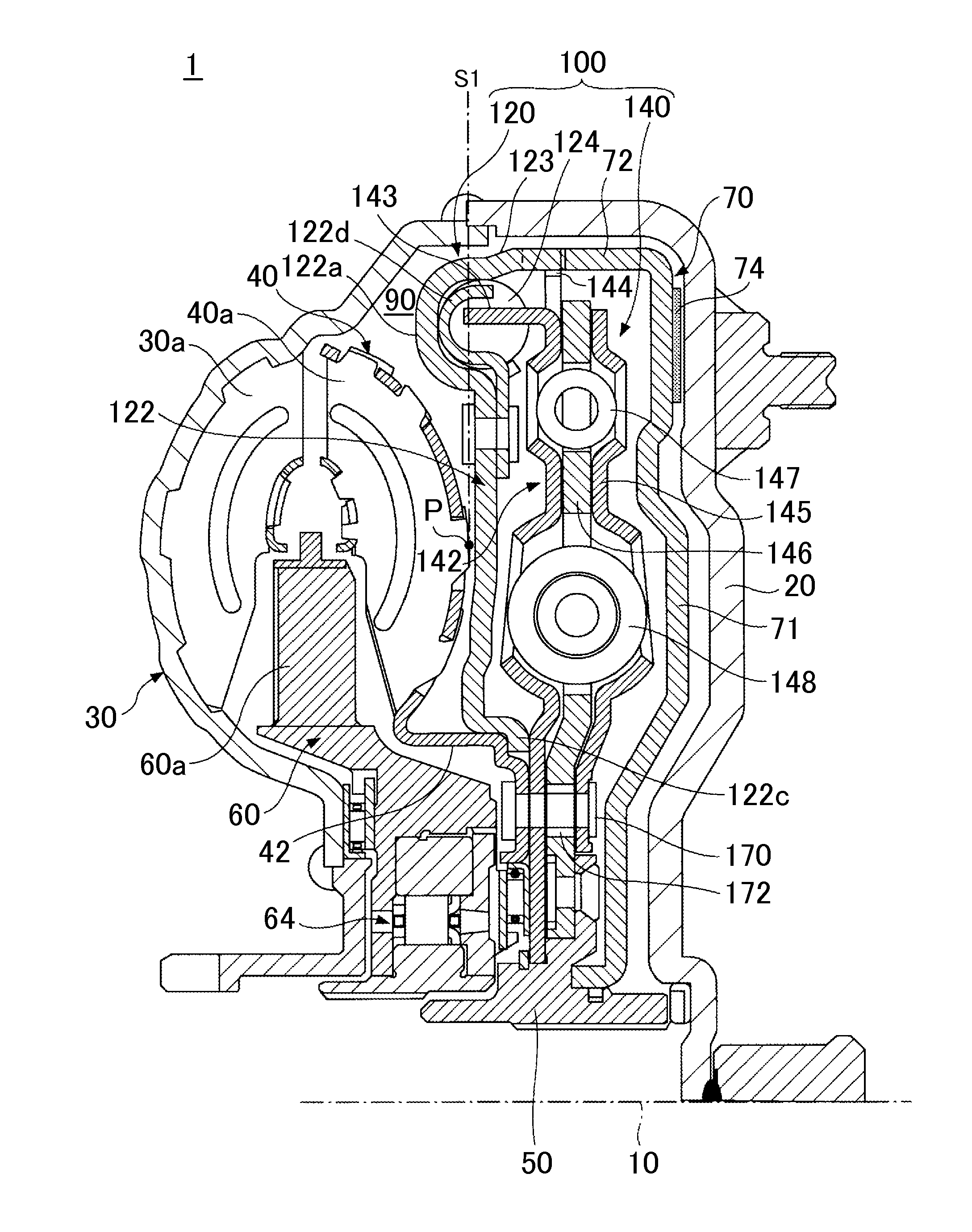
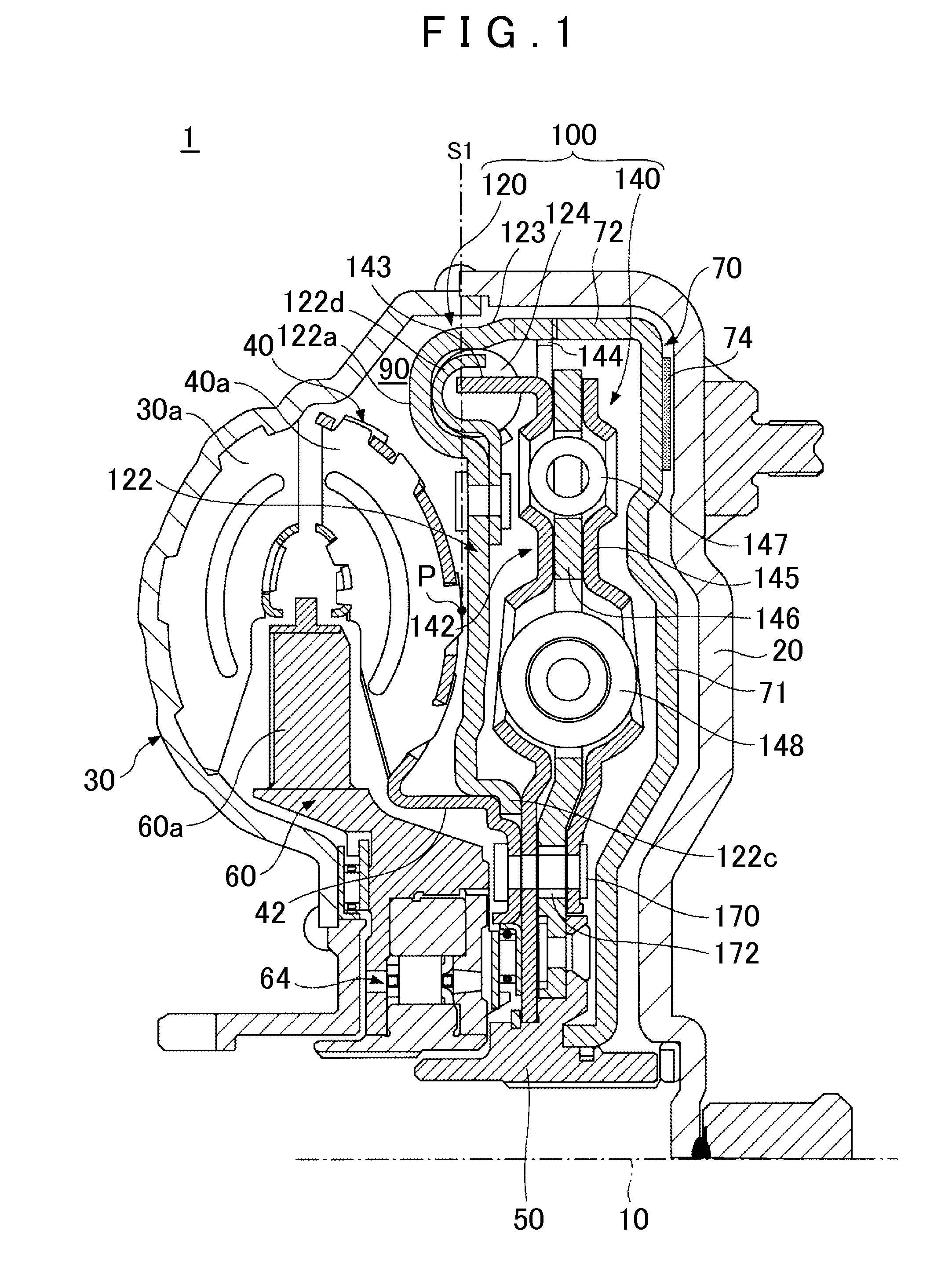
[0020]FIG. 1 is a cross-sectional view showing the configuration of an essential portion of a starting device 1 according to Reference Example 1. In FIG. 1, the upper half of a cross section of the starting device 1 (the upper half above an input shaft 10) is shown. In the following description, the term “axial direction” refers to the direction of the input shaft 10 of a transmission (the left-right direction of FIG. 1), and the term “radial direction” refers to the radial direction around the input shaft 10 of the transmission (the direction perpendicular to the input shaft 10; the up-down direction of FIG. 1, for example) as viewed along the input shaft 10 of the transmission. Thus, the term “radially outer side” or “outer circumferential side” refers to the side away from the input shaft 10 in the direction perpendicular to the input shaft 10, and the term “radially inner side” refe...


PUM


Abstract

A starting device includes: a lock-up clutch mechanism; a fluid coupling; a spring damper including a spring, a power transfer portion transferring power from the lock-up clutch mechanism to the spring, and a power output portion transferring power from the spring to an input shaft; and a pendulum damper including a pendulum and a pendulum power transfer portion transferring power from the spring damper to the pendulum. The output portion of the lock-up clutch, the pendulum damper, the spring damper, and the fluid coupling are arranged sequentially in this order from a motor in the axial direction. The lock-up clutch mechanism output and the spring damper output are connected to each other on the outer circumferential side of the pendulum damper, and the spring damper output and the pendulum power transfer portion are connected to each other on the inner circumferential side of the pendulum.

Description

INCORPORATION BY REFERENCE[0001]The disclosure of Japanese Patent Application No. 2010-221024 filed on Sep. 30, 2010 including the specification, drawings and abstract is incorporated herein by reference in its entirety.BACKGROUND OF THE INVENTION[0002]The present invention relates to a starting device that is disposed between a motor and a transmission.DESCRIPTION OF THE RELATED ART[0003]Hitherto, there has been known a configuration in which a damper device that relieves and absorbs impact torque or the like is disposed on a motor side with respect to a turbine runner of a starting device in the axial direction (see Japanese Patent Application Publication No. 2009-243536, for example). In such a configuration, however, a space on the outer circumferential side of the turbine runner creates a dead space, and may not be utilized effectively.[0004]In order to effectively utilize such a dead space, there has been developed a configuration in which a new damper forming element is dispo...

Claims


Application Information

Patent Timeline
IPC IPC(8): F16D33/18
CPCY10T74/2128F16H2045/0205F16F15/145F16H2045/0221F16H45/02F16H2045/0231F16H2045/0263F16H2045/0294
Inventor ITO, KAZUYOSHINAGAE, AKIHIROMORI, YOSHIHIDEARAKI, KEIZO
Owner AISIN AW CO LTD
Why Eureka
Try Eureka