Charged Particle Source with Integrated Electrostatic Energy Filter

a technology of electrostatic energy filter and charge particle source, which is applied in the direction of instruments, mass spectrometers, beam deviation/focusing by electric/magnetic means, etc., can solve the problems of complex machining and alignment of mechanical parts forming these hemispherical capacitors

Active Publication Date: 2012-05-10
FEI CO
View PDF2 Cites 11 Cited by
  • Summary
  • Abstract
  • Description
  • Claims
  • Application Information

AI Technical Summary

Problems solved by technology

It is a disadvantage of the known source that the hemispherical capacitors are off-axial, and both machining and aligning the mechanical parts forming these hemispherical capacitors is complicated.
According to this application the skilled person (the expert) must first select a shape for the axis of the monochromator, e.g. an Ω or an α, resulting in a similar disadvantage as described for the U.S. Pat. No. 6,770,878.

Method used


Image

  • Charged Particle Source with Integrated Electrostatic Energy Filter
  • Charged Particle Source with Integrated Electrostatic Energy Filter
  • Charged Particle Source with Integrated Electrostatic Energy Filter

Examples


first embodiment

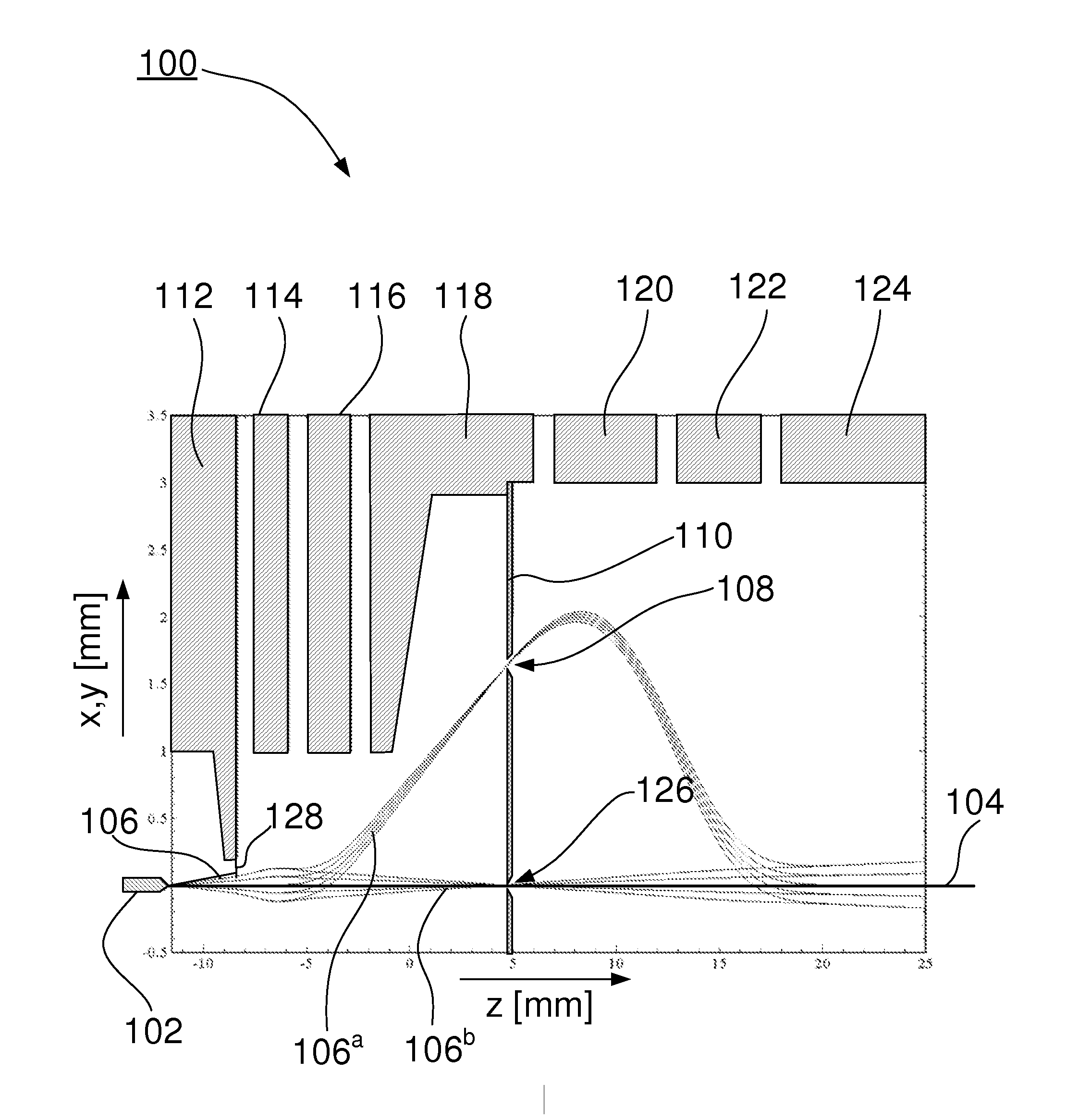
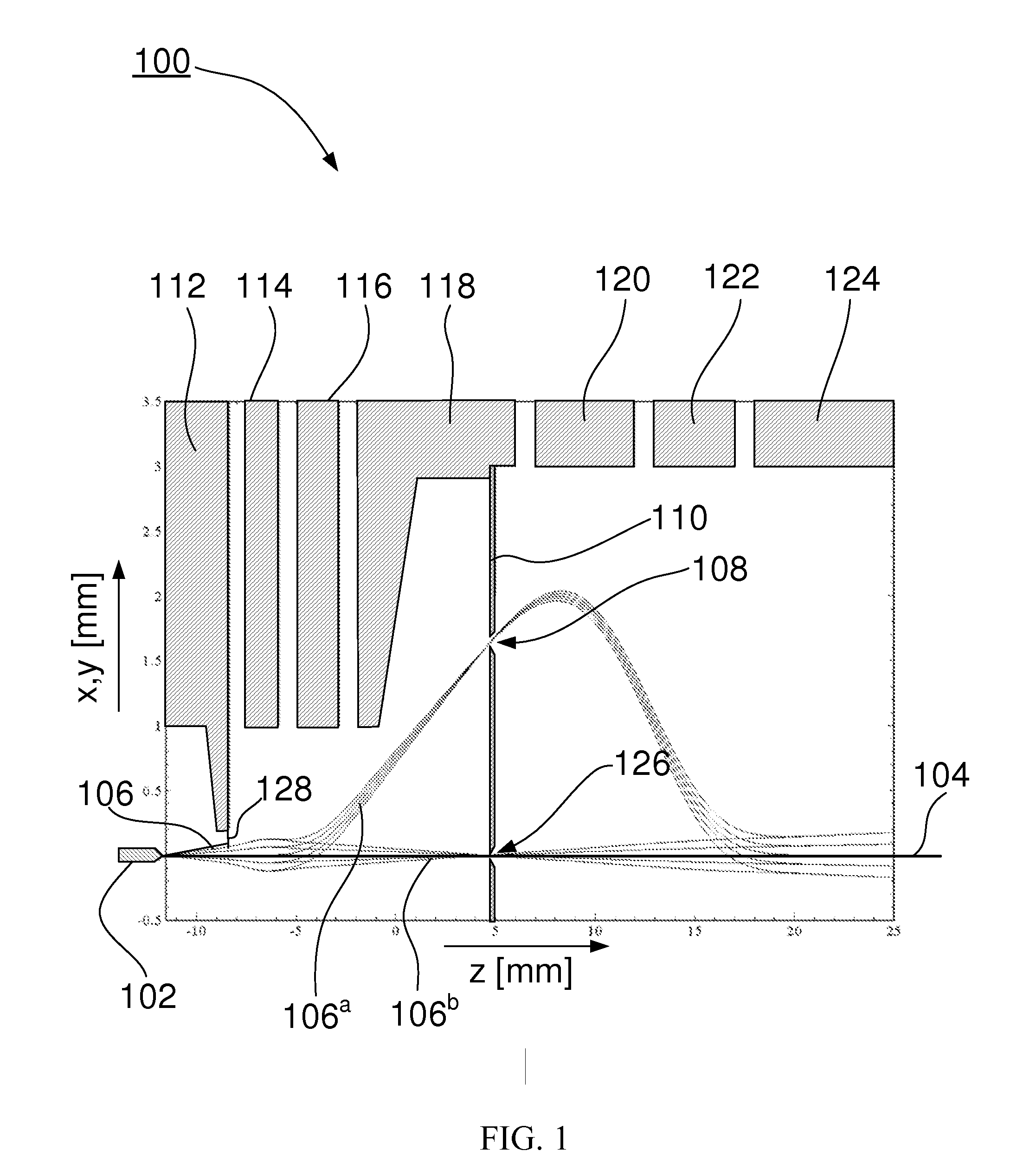
[0042]FIG. 1 shows the particle source according to the invention. FIG. 1 shows a particle source 100 comprising a charged particle emitter 102, in this embodiment a Schottky emitter. Due to an extraction field produced by extractor 112 the emitter emits a beam of charged particles 106 round axis 104. Extractor 112 also acts as a beam limiting aperture, transmitting only part of the current emitted by the emitter. As the beam is deflected in the x-direction, a projection of the beam is shown on the x-plane, projection 106a, and on the y-plane, projection 106b. The beam is focused on energy selective diaphragm 110 as a result of axial focusing fields generated between electrodes 112, 114 and 116. It is noted that these electrodes do not form a uni-potential lens, in other words: the energy with which the electrons leave electrode 116 is not the same as with which they enter electrode 112. The beam is deflected from the axis by a deflection field generated by electrode 116, and is dir...

second embodiment

[0060]Table 2 gives an overview of the excitations, here also referred to as the Fourier voltages) used on the different electrodes for the invention.

TABLE 2electrode excitations [Fourier voltage] for the second embodiment.Round lens excitationDipoleQuadrupolewith respect to emitterexcitationexcitationElectrode[Fourier voltage][Fourier voltage][Fourier voltage]1124600——1145584.7—1161000124  3.41181000——1201741−78656122103356418124727——

[0061]It is mentioned that, as the pre-slit optics are identical to the first embodiment, for a Schottky emitter the Coulomb interactions of this embodiment are also negligible when the current transmitted by the extractor (electrode 112) is less than approximately 30 nA.

[0062]FIG. 3 shows a 120° / 60° / 120° / 60° segmented electrode. The electrode shows 4 segments 301 . . . 304, with a central bore 305 arranged round axis 104. The first segment 301 is a 120° electrode, arranged at φ=0. Another 120° segment, segment 303, is arranged at φ=π. The two remainin...

third embodiment

[0065]FIGS. 4A and 4B schematically show the particle source according to the invention, in which FIG. 4A schematically shows the electrode lay-out and FIG. 4B schematically shows the rays.

[0066]FIG. 4A shows a particle source 100 comprising a charged particle emitter 102. Extractor 112 extracts electrons from the emitter. Electrode 402 deflects the beam of electrons from the axis, while electrode 404 deflects the beam back into the direction of the axis. Drift electrode 406 acts, together with electrode 404 and electrode 402, as a lens, while the “interior” of the electrode acts as a drift space. A focus is formed at the position of the energy selecting diaphragm 110. Electrode 408 bends the beam parallel to the axis, so that the beam exiting the source is parallel and aligned with the beam emitted by the emitter. After electrode 408 a further drift electrode 410 is placed, said further drift having identical voltages on all electrodes as drift electrode 406, and the two drift elec...


PUM


Abstract

A charged particle filter with an integrated energy filter, in which the charged particle emitter, the focusing electrodes, and the deflection electrodes are arranged round a straight axis. Where most energy filters used have a highly curved optical axis, and thus use parts with forms that are difficult to manufacture, the source according the invention uses electrodes surrounding a straight optical axis. A beam of charged particles can be deflected quite far from the axis showing respectable energy dispersion at an energy selecting slit without introducing coma or astigmatism that cannot be corrected, provided that some of the are formed as 120°/60°/120°/60°. Such electrodes can be attached to each other by gluing or brazing of ceramic, and then series of a highly concentric bores can be formed by, e.g., spark erosion.

Description

[0001]This Application claims priority from U.S. Provisional Application 61 / 412,065, filed Nov. 10, 2010, which is hereby incorporated by reference.TECHNICAL FIELD OF THE INVENTION[0002]The invention relates to a charged particle source with integrated electrostatic energy filter.BACKGROUND OF THE INVENTION[0003]Such a particle source is known from U.S. Pat. No. 6,770,878, describing a charged particle source with an integrated omega filter. The charged particle source comprises an ion or electron emitter, such as a Schottky emitter, emitting charged particles in a cone along an axis. A beam defining aperture selects an axial part of the beam, and focusing electrodes image the source further on along the axis. A first hemispherical capacitor acting as a deflector bends the axis, followed by a second hemispherical capacitor bending the axis parallel to its original direction, but displaced. A third and a fourth hemispherical capacitor bend the axis back so that it is both parallel an...

Claims


Application Information

Patent Timeline
Patent Type & Authority Applications(United States)
IPC IPC(8): H01J3/26H01J3/14
CPCH01J37/05H01J37/06H01J37/08H01J37/09H01J2237/31713H01J37/28H01J2237/0453H01J2237/053H01J2237/057H01J37/26
Inventor HENSTRA, ALEXANDER
Owner FEI CO
Why Eureka
Try Eureka