Light Emitting Diode with Polarized Light Emission

a light-emitting diode and light-emitting technology, applied in the direction of basic electric elements, semiconductor devices, electric devices, etc., can solve the problems of high cost, polarizers add cost and complexity to such displays, and none of these methods are compatible with mass production of leds

Inactive Publication Date: 2012-05-10
AGENCY FOR SCI TECH & RES
View PDF10 Cites 23 Cited by
  • Summary
  • Abstract
  • Description
  • Claims
  • Application Information

AI Technical Summary

Problems solved by technology

The polarizer adds cost and complexity to such displays.
Yet, none of these methods are compatible with mass production of LEDs.
In addition, these methods result in high cost, complex LED designs which are sensitive to parameter changes and have a low polarization ratio.

Method used


Image

  • Light Emitting Diode with Polarized Light Emission
  • Light Emitting Diode with Polarized Light Emission
  • Light Emitting Diode with Polarized Light Emission

Examples


Embodiment Construction

[0017]The following detailed description is merely exemplary in nature and is not intended to limit the invention or the application and uses of the invention. Furthermore, there is no intention to be bound by any theory presented in the preceding background of the invention or the following detailed description of the invention.

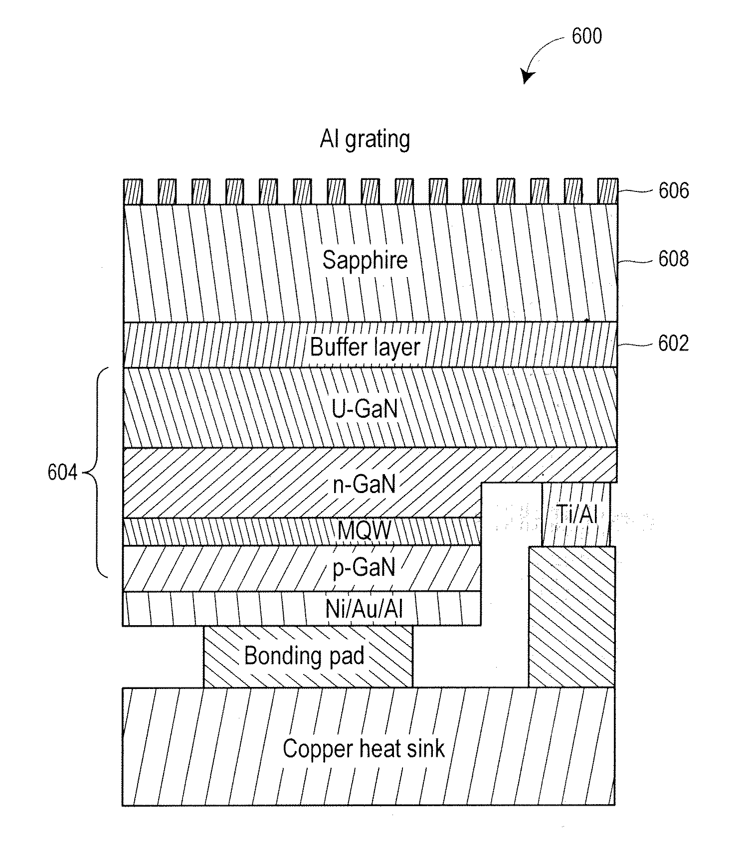
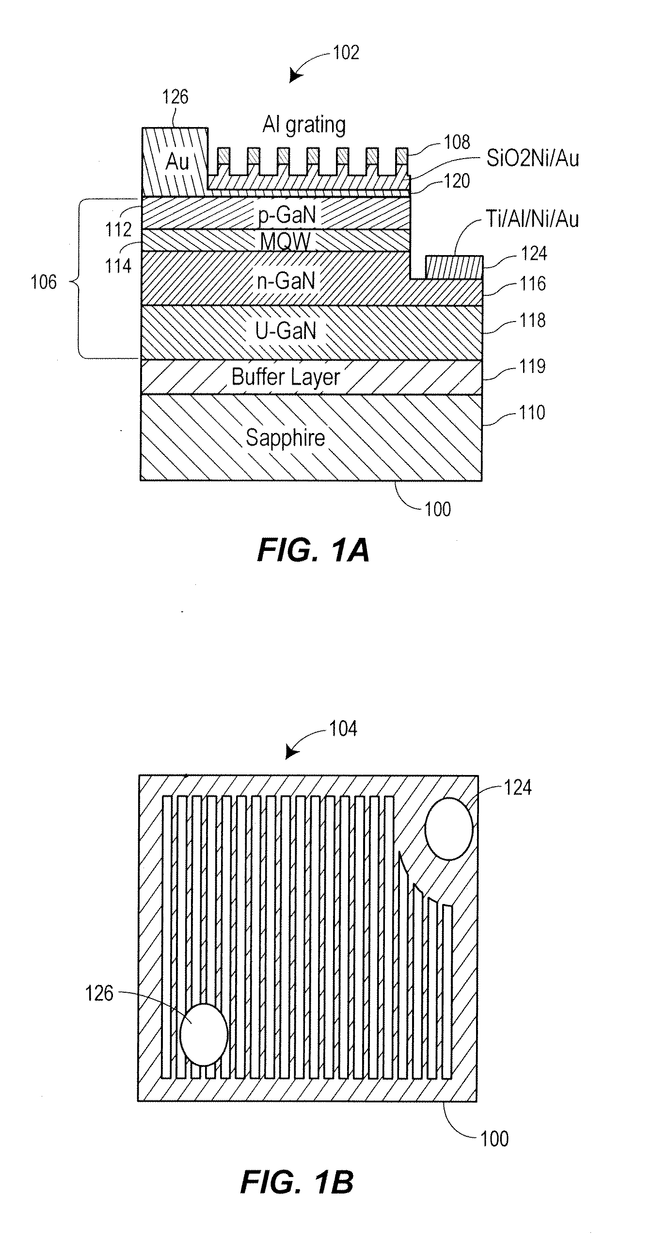
[0018]Referring to FIG. 1, an apparatus 100 for emitting polarized light in accordance with a present embodiment is depicted. FIG. 1A is a side planar view 102 of the apparatus 100, while FIG. 1B is a top planar view 104 of the apparatus 100. The apparatus 100 includes a surface emission light emitting diode (LED) 106 with a sub-wavelength metal grating (SWMG) 108. The LED 106 structure is grown on a (0001) sapphire substrate 110 by metal organic chemical vapor deposition. The layered structure of the LED 106 has an approximately two hundred nanometer (200 nm) thick p-GaN layer 112, quantum wells 114, an approximately two thousand nanometer (2000 nm) thick n...


PUM


Abstract

An apparatus for emitting polarized light and a method for fabricating such apparatus are provided. The apparatus includes a surface emission light emitting diode (LED), a first electrode, and a sub-wavelength metal grating (SWMG). The surface emission LED includes a first contact surface and a second contact surface. The first electrode is coupled to the first contact surface. The SWMG is formed on a surface of the surface emission LED.

Description

TECHNICAL FIELD[0001]The present invention generally relates to light emitting diodes (LEDs), and more particularly relates to LEDs with polarized light emission.BACKGROUND OF THE DISCLOSURE[0002]Light emitting diodes (LEDs) have become important light sources in many applications such as solid state lighting, back lighting, signaling and displays. The increase in importance of LEDs to these applications is due in part to the success of InGaN materials and LED device development. As in conventional light sources, the LEDs are non-coherent and non-polarized light sources, i.e. light does not possess a significant preference for a specific polarization state. However, for some applications, such as LCD backlighting, LCD projection, and liquid crystal (LC)-beam steering devices in which the light beam emitted by LED point sources is manipulated with LC cells, the non-polarized light from LEDs must be converted to polarized light through a polarizer in order for the next layer of LC to ...

Claims


Application Information

Patent Timeline
Patent Type & Authority Applications(United States)
IPC IPC(8): H01L33/38
CPCH01L33/38H01L2933/0091H01L33/508H01L33/46
Inventor TENG, JINGHUACHUA, SOO-JINZHANG, LIANGDENG, LIYUAN
Owner AGENCY FOR SCI TECH & RES
Why Eureka
Try Eureka