
Axial face seal assembly

Active Publication Date: 2012-05-10
XYLEM IP HLDG
View PDF4 Cites 1 Cited by
  • Summary
  • Abstract
  • Description
  • Claims
  • Application Information

AI Technical Summary

Benefits of technology

[0011]Thus, the present invention relates to the insight that a wear protection means located at the torque transmitting interface of the torque driver means will substantially improve the working life of the axial face seal assembly, since the direct contact and wear of the torque driver means are prevented.
[0015]In a preferred embodiment the moving part comprises a carrier that comprises three torque driver pins equidistantly spaced in the circumferential direction, and one wear protection pin is arranged at the trailing side of each torque driver pin in the direction of rotation of the drive shaft. Due to the use of three torque driver pins the abutment load in the circumferential direction on each torque driver pin is reduced.

Problems solved by technology

However, when the axial face seal assembly is mounted in a submersible pump, suitable for pumping contaminated liquid, it will experience relative movement between the base element and the carrier in the axial direction due to thermal expansion, vibrations, obliquity, etc.
In course of time each dowel and dowel hole will wear on each other, i.e. the dowel will tear a slot in the corresponding dowel hole at the torque transmitting interface and the dowel hole will wear on the side of the dowel facing the torque transmitting interface.
As a result said side of the dowel will be rough and irregular and the upper edge of the dowel hole may get caught on any undesired irregularity on the dowel.
Thus, the wear will obstruct the axial movement of the carrier / seal member in relation to the base element.
As a result the axial face seal assembly will often cause the axial face seal to become overloaded and break or become opened and leak.

Method used


Image

  • Axial face seal assembly
  • Axial face seal assembly
  • Axial face seal assembly

Examples


Embodiment Construction

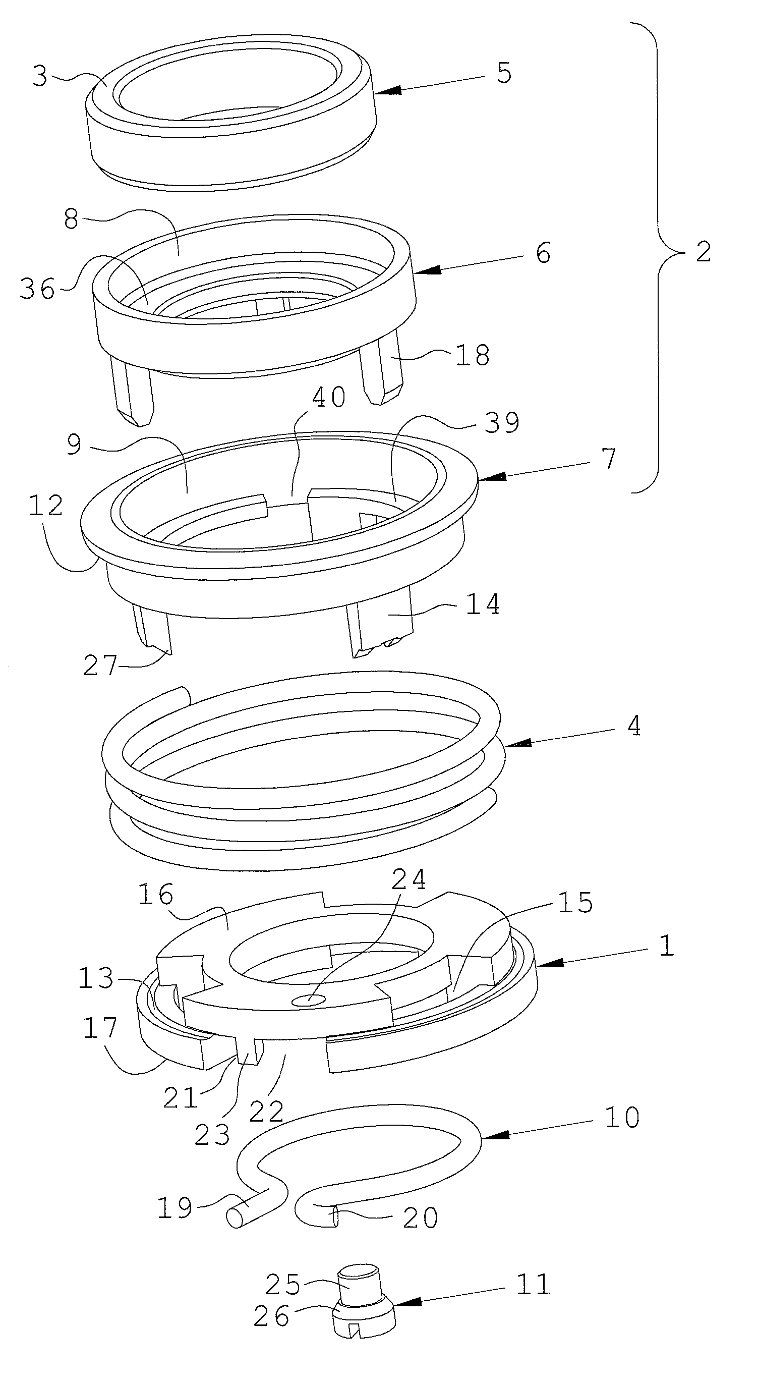
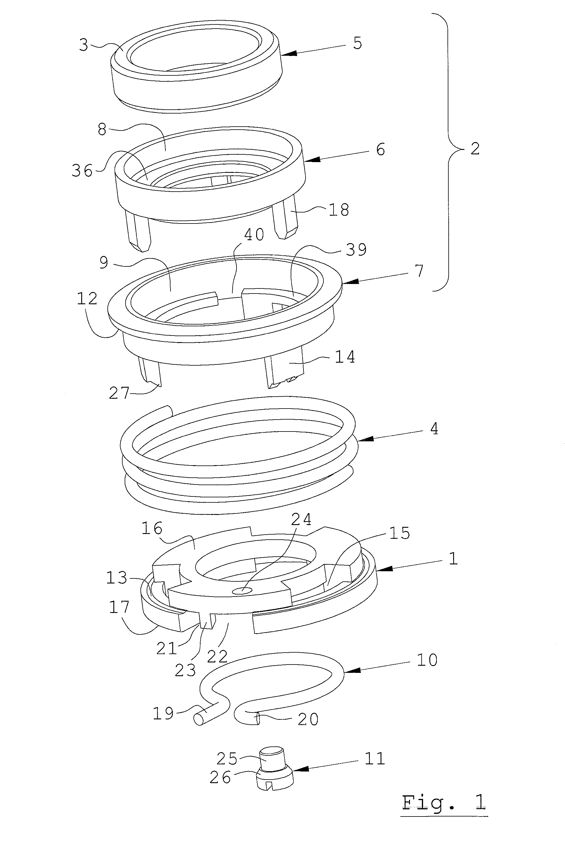
[0022]The components comprised in a preferred embodiment of the inventive axial face seal assembly are illustrated in the exploded perspective view FIG. 1. The components are shown in consecutive order from top to bottom of the drawing.

[0023]According to aspects of the invention, the axial face seal assembly is arranged for joint rotation with a drive shaft in a rotary machine, and comprises a base element 1 and a moving part 2. The base element 1 is connectable to a drive shaft (not shown) for joint movement therewith, and the moving part 2 present a sealing end face 3 and is axially movable in relation to the base element 1 and biased from the base element 1 by means of a spring 4.

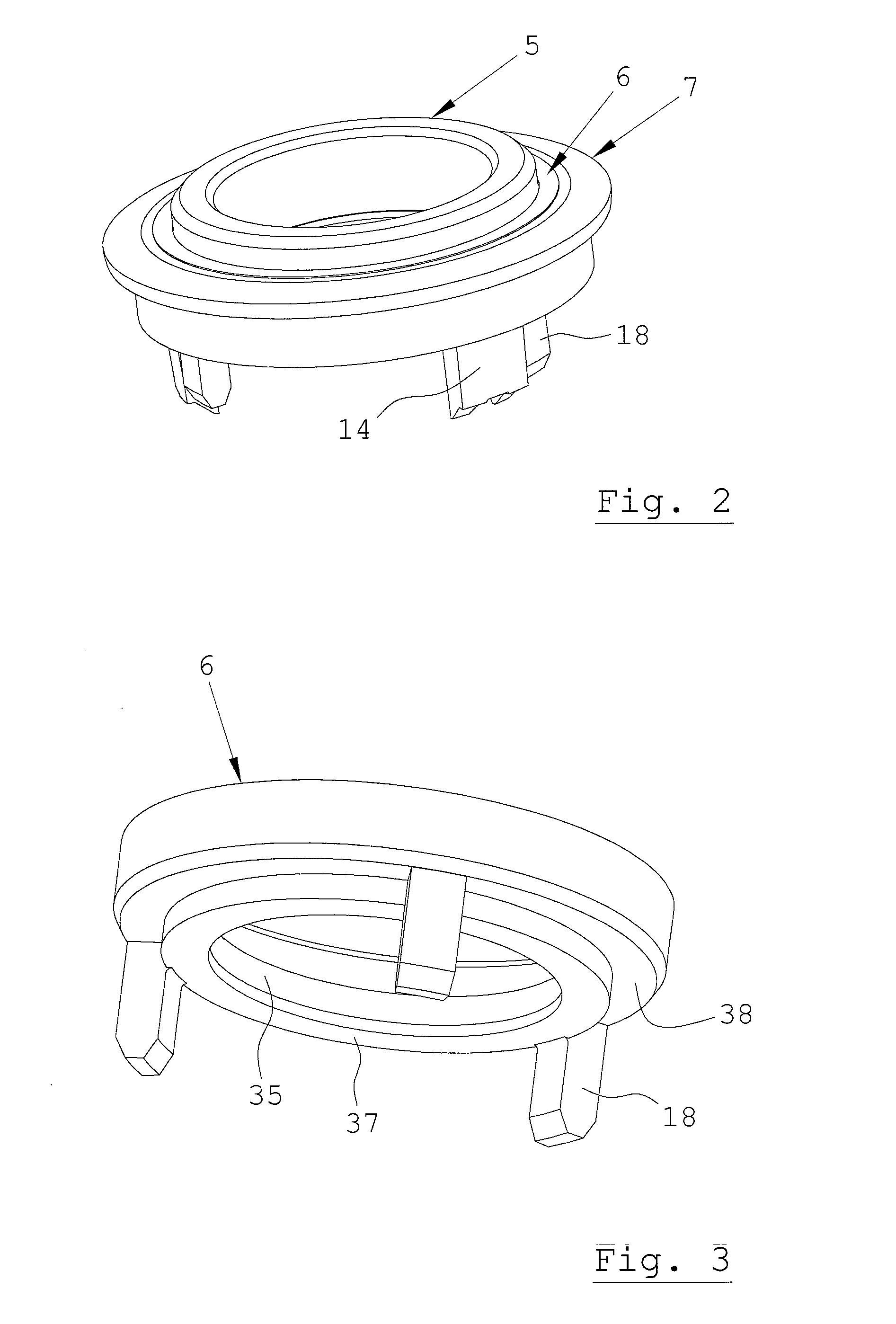
[0024]In a preferred embodiment of the axial face seal assembly, the movable part 2 comprises an annular seal member 5 presenting the sealing end face 3 at its top surface, an elastic sleeve 6, which is made of a heat resistant material in order to withstand the heat which is generated during operation o...


PUM


Abstract

An axial face seal arrangement, which is arranged for joint rotation with a drive shaft in a rotary machine, includes a base element and a moving part, wherein the base element is connectable to a drive shaft for joint movement therewith, the moving part presenting a sealing end face and being axially movable in relation to the base element and biased from the base element by a spring, wherein the moving part and the base element include at least one torque driver pin and at least one corresponding aperture into which the torque driver pin is displacably inserted for joint rotational movement of the moving part with the base element. At least one wear protection pin is arranged between the torque driver pin and the aperture at a force transmitting interface of the torque driver pin and the aperture.

Description

CROSS REFERENCE TO RELATED APPLICATIONS[0001]This application is the U.S. National Stage Patent Application of PCT / SE2010 / 050494, filed May 5, 2010, which claims priority to Swedish Patent Application No. SE 0950325-1, filed May 11, 2009, the contents of such applications being incorporated by reference herein.FIELD OF THE INVENTION[0002]The present invention relates generally to the field of seal assemblies arranged for joint rotation with a drive shaft of a rotary machine. Further, the present invention relates specifically to the field of axial face seal assemblies which effects sealing of the passage of a drive shaft through a housing wall in the rotary machine. The axial face seal assembly comprises a base element and a moving part, wherein the base element is connectable to a drive shaft for joint movement therewith, the moving part presenting a sealing end face and being axially movable in relation to the base element and biased from the base element by means of a spring, whe...

Claims


Application Information

Patent Timeline
IPC IPC(8): F16J15/34F16J15/38
CPCF04D29/126F16J15/348F16J15/3452F16J15/3464
Inventor JOHANSSON, JOHANNAFONDELIUS, JOHAN
Owner XYLEM IP HLDG
Learn More