Energy Storage Devices and Methods of Using Same

a technology of energy storage and energy storage devices, which is applied in the field of energy storage, can solve the problems of excessive wear and tear of machinery, difficult to match the output of generation to the electrical demand of the grid operator, and the difficulty of running combustion turbines at different speeds, etc., and achieve the effect of storing potential energy

Inactive Publication Date: 2012-05-10
MURRAY SABEN +2
View PDF10 Cites 47 Cited by
  • Summary
  • Abstract
  • Description
  • Claims
  • Application Information

AI Technical Summary

Benefits of technology

[0010]The invention is directed to various energy storage devices and systems and methods of using the same. The energy storage device takes advantage of the height difference between the bottom and the surface of a body of water. The energy storage device utilizes the movement of a mass or multiple masses, such as weights or floats, to store energy as potential energy and to generate energy by releasing the potential energy. Weights attached to tethers are pulled toward the surface o...

Problems solved by technology

As more and more sources of intermittent generation from renewable sources like the wind and sun are integrated into the electric grid, the critical task of matching generation output to electrical demand for which grid operators are responsible becomes more and more difficult.
Running combustion turbines at varying speeds, however, is inefficient and causes excess wear and tear on the machinery.
As a larger and larger fraction of the world's energy is derived from intermittent sources, more and more combustion turbines running under these non-optimal conditions will be required, presenting an ever-larger and more costly problem to utilities.
To turn renewables into a dispatchable resource, however, requires a huge amount of storage.
Existing energy storage technologies fall short of being able to perform this function economically.
The ubiquitous lead-acid battery has a low sticker price but is inefficient and limited in its usable depth of discharge.
It also has short cycle life, which requires it to be replaced often.
Advanced flow and lithium-ion batteries improve upon the cycle-life and usable depth of discharge but are very...

Method used


Image

  • Energy Storage Devices and Methods of Using Same
  • Energy Storage Devices and Methods of Using Same
  • Energy Storage Devices and Methods of Using Same

Examples


Embodiment Construction

[0044]Various embodiments of the invention are described below in conjunction with the Figures. However, this description should not be viewed as limiting the scope of the present invention. Rather, it should be considered as exemplary of various embodiments that fall within the scope of the present invention as defined by the claims. Further, it should also be appreciated that references to “the invention” or “the present invention” should not be construed as meaning that the description is directed to only one embodiment or that every embodiment must contain a given feature described in connection with another embodiment or described in connection with the use of such phrases. In fact, various embodiments with common and differing features are described herein.

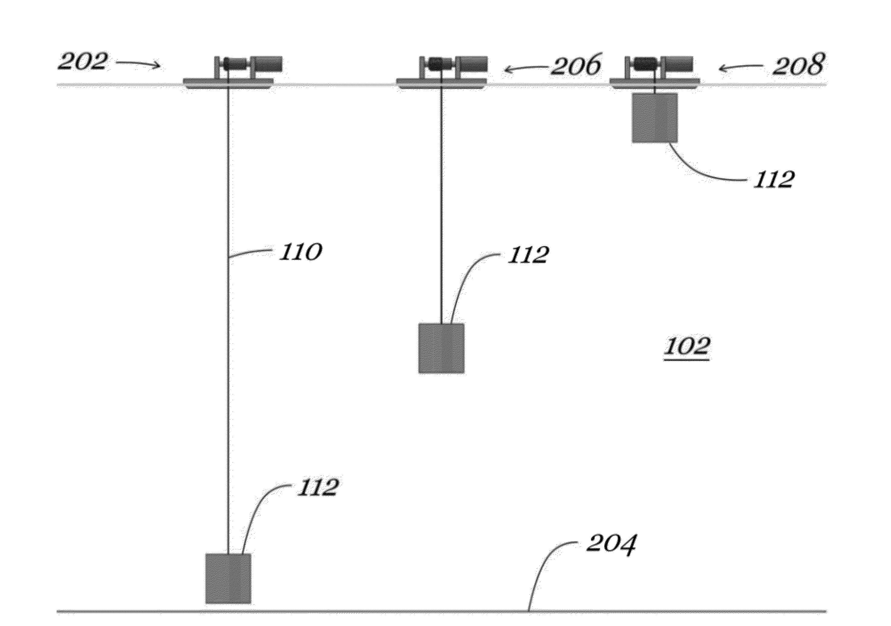
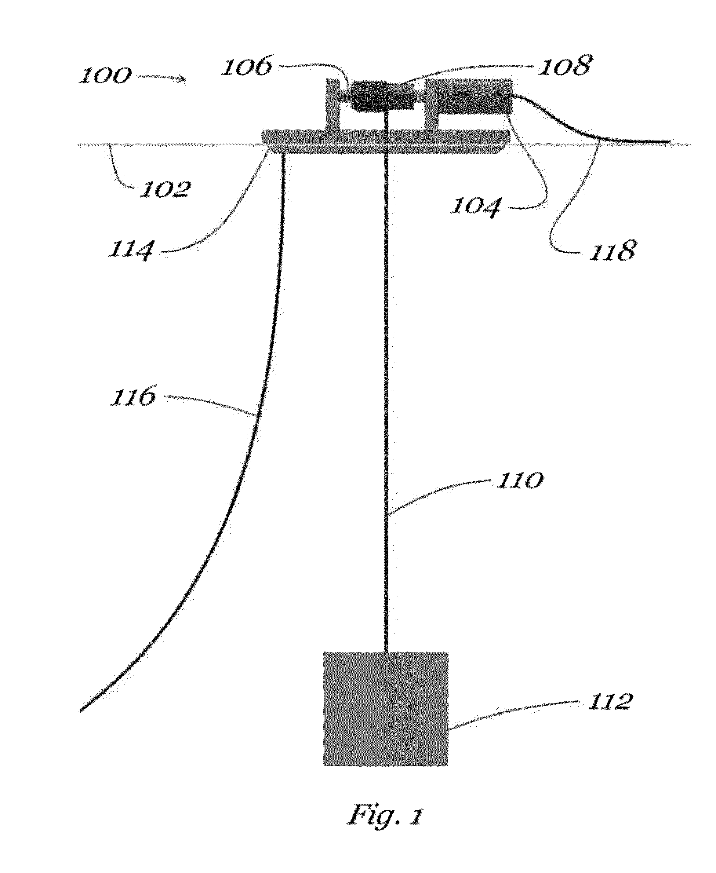
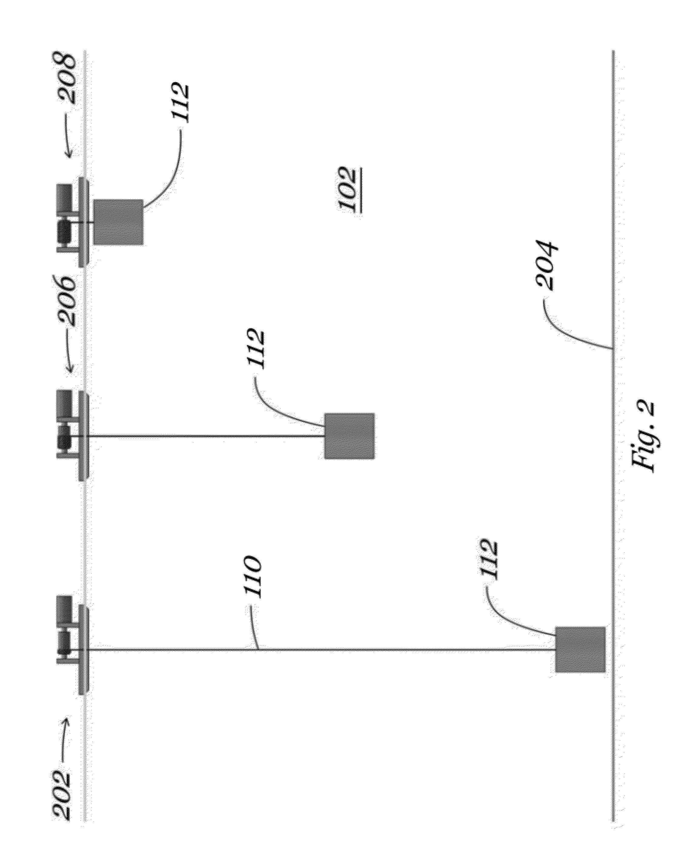
[0045]The present invention is generally directed to various embodiments of an energy storage device and methods of using the device to store energy mechanically using gravitational potential. Basically, energy to be stored ...


PUM


Abstract

The invention is directed to various energy storage devices and methods of using the same. The energy storage device takes advantage of the height difference between the bottom and the surface of a body of water. The energy storage device utilizes the movement of a mass, such as weights or floats, to store energy as potential energy and to generate energy by releasing the potential energy. Weights attached to tethers are pulled toward the surface of the water by a motor/generator powered by energy to be stored, thereby storing potential energy. Allowing the weights to fall downward releases the potential energy and reverses the motor/generator to generate electricity. Floats attached to tethers are pulled toward the bottom of the water by a motor/generator powered by energy to be stored, thereby storing potential energy. Allowing the floats to rise releases the potential energy and reverses the motor/generator to generate electricity.

Description

CROSS-REFERENCE TO RELATED APPLICATIONS[0001]This application claims the benefit of provisional Application No. 61 / 381,727, filed Sep. 10, 2010 and of provisional Application No. 61 / 413,817, filed Nov. 15, 2010. The entirety of each of the foregoing applications is incorporated by reference herein.BACKGROUND OF THE INVENTION[0002]1. Field of the Invention[0003]The present invention is in the field of energy storage. More specifically, the present invention is directed various embodiments of an energy storage device and methods of using the device to store energy mechanically using gravitational potential by utilizing the height difference between the bottom and the surface of a deep body of water.[0004]2. Description of Related Art[0005]As more and more sources of intermittent generation from renewable sources like the wind and sun are integrated into the electric grid, the critical task of matching generation output to electrical demand for which grid operators are responsible beco...

Claims


Application Information

Patent Timeline
IPC IPC(8): H02K7/18
CPCH02J15/003Y02E60/17F03B13/1885F03B13/1865F03B13/1815F03B13/1845Y02E10/30Y02E60/16
Inventor MURRAY, SABENTURNBULL, III, WILLIAMBREINGAN, WILLIAM
Owner MURRAY SABEN
Why Eureka
Try Eureka