Wireless power system and method with improved alignment

a wireless power supply and portable device technology, applied in the direction of magnets, inductances, magnets, etc., can solve the problems of difficult to achieve consistent alignment between primary and secondary coils, components are prone to mechanical failure, and multiple coil arrays are expensive to implement. achieve the effect of improving power transfer efficiency, cost-effectiveness and simple and effectiv

Active Publication Date: 2012-05-10
PHILIPS IP VENTURES BV
View PDF6 Cites 139 Cited by
  • Summary
  • Abstract
  • Description
  • Claims
  • Application Information

AI Technical Summary

Benefits of technology

[0023]The present invention provides a simple and effective wireless power system that aids alignment of a portable device relative to an inductive power supply for improving power transfer efficiency. The wireless power system may utilize a wireless induction coil to produce a temporary DC magnetic field. This may be a cost effective and reliable alignment aid for wireless power systems. Indeed, the existing wireless induction coils, such as the primary, secondary, or both coils, may be used as an alignment aid.

Problems solved by technology

Absent some additional information, the user may find it difficult to achieve consistent alignment between the primary and secondary coils and therefore efficient power transfer.
However, multiple coils arrays tend to be expensive to implement, which in many cases makes them an inappropriate solution for achieving close alignment between a primary coil and a secondary coil.
As a result of this physical movement used in the movable coil system, components may be prone to mechanical failure.
Nested coils, such as one or more coils nested within another coil, may limit the interoperability of the inductive charger.
First, permanent magnets may heat up in the presence of an AC magnetic field, causing undesired heat transfer to nearby components.
Second, the amount of force used to align the portable electronic device with the inductive power supply may be large.
Larger magnetic forces can correlate to larger permanent magnets, and space within the portable electronic device or the inductive power supply may be limited.
Permanent magnets also can be expensive.
Third, permanent magnets may attract surrounding objects, such as paper clips, which can cause a poor user experience with the inductive wireless power system.
A fourth limitation may be the DC magnetic flux produced from the permanent magnets.
Further, the presence of DC magnetic flux can lower the saturation point of magnetic shielding materials.
These magnetic shielding materials may be used to guide the AC flux of the inductive charging system, and a lower saturation point means that more AC flux may be lost.
Lastly, balancing characteristics of permanent magnets may include performance trade-offs.
On the other hand, magnets that are too strong may result in the inductive charger being lifted off the table when the portable device is picked up.

Method used


Image

  • Wireless power system and method with improved alignment
  • Wireless power system and method with improved alignment
  • Wireless power system and method with improved alignment

Examples


second embodiment

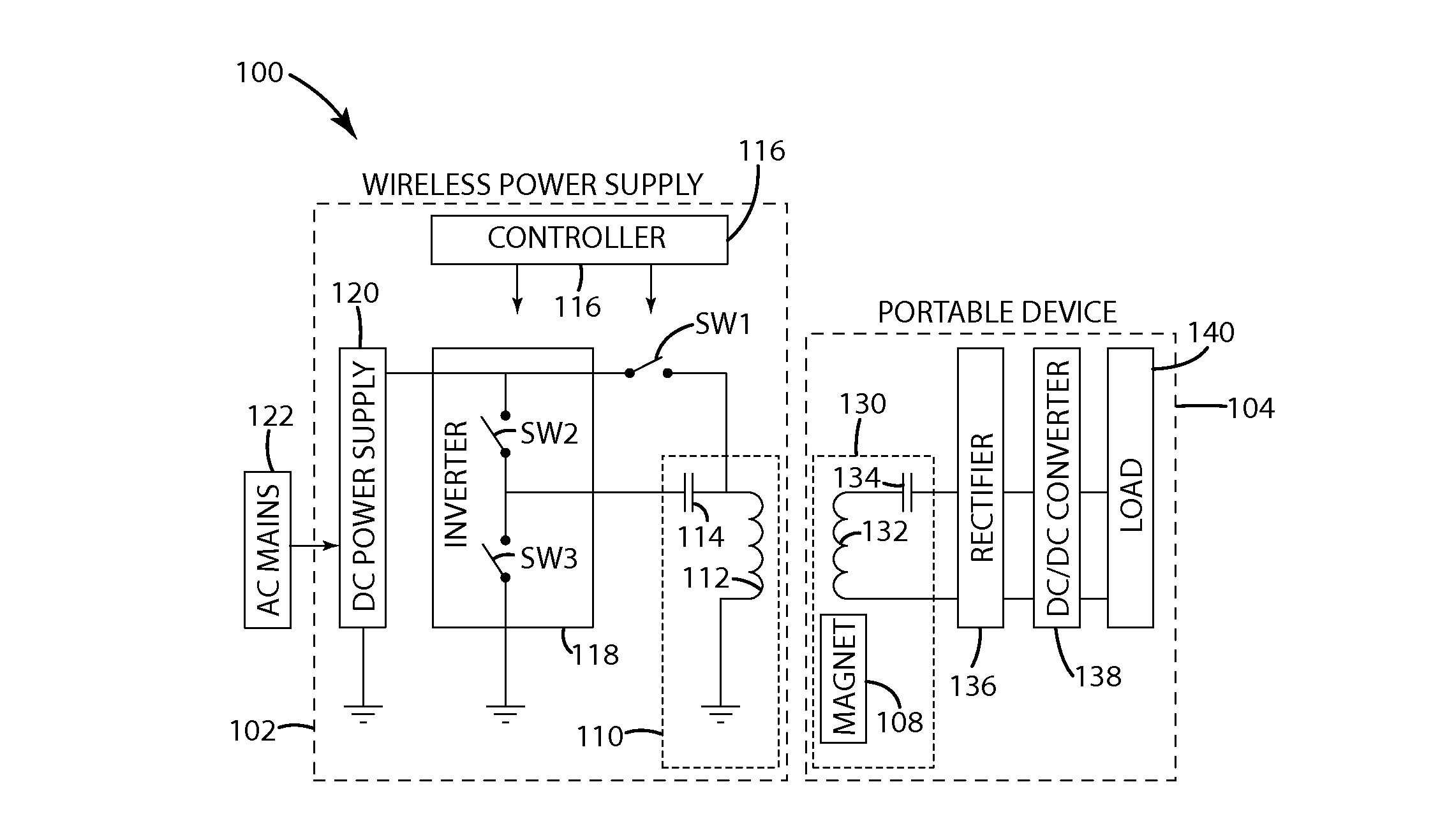
[0059]Referring now to FIG. 3, the physical configuration of the DC coil drive system 400 is shown. The DC coil drive system 400 includes components similar to the embodiments described with regard to FIGS. 2a-c. The primary coil 312 in this configuration is shown with an associated primary magnet 306, which may be located near the center of the primary coil 312. The primary magnet 306 may be similar to the primary magnet described above. The primary coil 312 may act as an inductive power transfer coil when driven with an AC current, and may act as an electromagnet that interacts with the secondary coil 332 when driven with a DC current. The secondary coil 332 in this configuration is shown without an associated secondary magnet, and may be used to generate a DC magnetic field for magnetic attraction.

[0060]Also shown in FIG. 3 are possible coil configurations for primary coil 312 and secondary coil 332. The inductive power supply may include a primary inductor or inductive element c...

third embodiment

[0061]Turning to the DC coil drive system 500 illustrated in FIG. 5, primary coil 312 and secondary coil 332 are both shown without associated magnets. The DC coil drive system 500 may include components similar to the embodiments described with regard to FIGS. 2a-c. Both the primary coil 312 and the secondary coil 332 in this configuration may generate a DC magnetic field in response to a DC current. When the two fields are in the same direction, an attractive force may help to urge alignment of the two coils. After an alignment operation occurs, an AC current may be applied to the primary coil 312 to transfer power inductively to the secondary coil 332.

[0062]As shown in FIG. 5, the third embodiment of the DC coil drive system may use primary inductor 12 and secondary inductor 32 to create an attractive force for alignment of the inductive power supply and electronic portable device. Primary inductor 12 may be similar to each of the primary inductors 112, 312, 412 described above, ...

fourth embodiment

[0070]The DC coil drive system of FIG. 8 illustrates a fourth embodiment that includes an inductive power supply with a primary inductor array 613. The primary inductor array 613 may include multiple primary inductors 612 that may be either individually energized or energized in groups to transfer power to an electronic portable device with a secondary inductor 632. The primary inductors 612 and secondary inductor 632 may be respectively similar to each of the primary inductors 12, 112, 312 and secondary inductors 32, 132, 332 described with regard to other embodiments. In alternative embodiments, primary inductors 612 may have associated primary magnets similar to the primary magnets 6, 106, 306 described in other embodiments. In yet further alternative embodiments, secondary inductor 632 may have an associated secondary magnet similar to the secondary magnets 8, 108, 308 described in other embodiments.

[0071]In the fourth embodiment, the primary inductor array 613 may be setup so t...


PUM


Abstract

A wireless power system that may align a portable electronic device with an inductive wireless power supply. The induction coils used for transferring power wirelessly may be used as DC electromagnets to align the portable electronic device with the inductive wireless power supply. A DC current may be supplied to the primary coil and to the secondary coil to generate DC electromagnetic fields and attractive force between the primary and secondary coils. This attractive force may be used for alignment.

Description

BACKGROUND OF THE INVENTION[0001]The present invention relates to systems and methods for aligning a portable device with an inductive wireless power supply, and more particularly to such systems that use magnetic attraction to align a portable device on an induction charging surface.[0002]Inductive wireless power supply systems include an inductive power supply with a primary coil and a portable device with a secondary coil. The inductive power supply may also include an inductive charging surface for placement of the portable device. In a typical situation involving this configuration, the portable device is placed on the inductive charging surface so that the primary coil and secondary coil are aligned and may inductively couple for wireless power transfer.[0003]In some applications, attempts have been made to place the secondary coil in close alignment and proximity to the primary coil located adjacent to the inductive charging surface. Alignment and proximity may affect the mut...

Claims


Application Information

Patent Timeline
Patent Type & Authority Applications(United States)
IPC IPC(8): H02J17/00
CPCH01F7/0247H02J5/005H01F38/14H02J50/90H02J7/0047H02J50/12H02J50/70
Inventor STONER, JR., WILLIAM T.MOORE, COLIN J.MOES, BENJAMIN C.SCHWANNECKE, JOSHUA K.BAARMAN, DAVID W.WEBER, RICHARD J.SCHAMPER, RYAN D.
Owner PHILIPS IP VENTURES BV
Why Eureka
Try Eureka