Bus bar of eps motor

a technology of eps motor and bus bar, which is applied in the field of bus bar of eps motor, can solve the problems of defect affecting the safety of operators, inability to easily perform insert molding operation, and inability to accurately fix the bus bar during molding work, etc., and achieve accurate fixing and molding work. , the effect of accurate fixing

Active Publication Date: 2012-05-10
LG INNOTEK CO LTD
View PDF7 Cites 39 Cited by
  • Summary
  • Abstract
  • Description
  • Claims
  • Application Information

AI Technical Summary

Benefits of technology

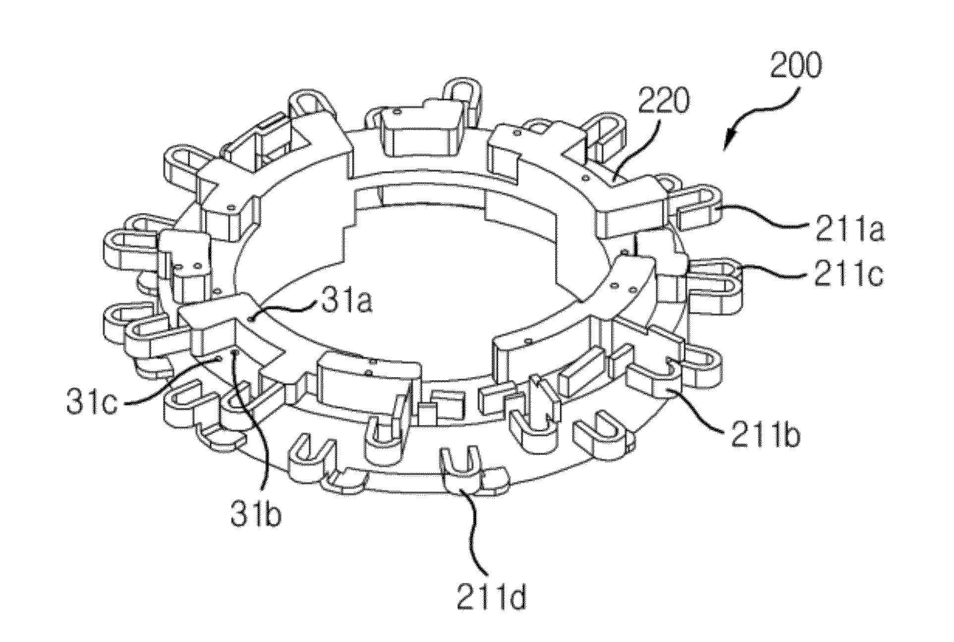
[0042]Preferably, the terminal includes an upper terminal arranged at an upper circumferential surface of the insulator and a lower terminal arranged at a lower circumferential surface of the insulator, wherein the fixing pin is lengthily and axially extended to penetrate upper and lower surfaces of the bus bar. Therefore, the bus bar can be accurately fixed during molding work even if the bent terminal is complicatedly structured.
[0043]The bus bar of an EPS motor thus configured according to the present disclosure is advantageous in that radial and circumferential positions can be accurately fixed during insert molding works of terminals of bus bar and body units, whereby insert molding works can be improved to enable an accurate molding of the bus bar.
[0044]Another advantage is that work efficiency in the manufacturing process can be increased to improve the operational reliability of bus bar.

Problems solved by technology

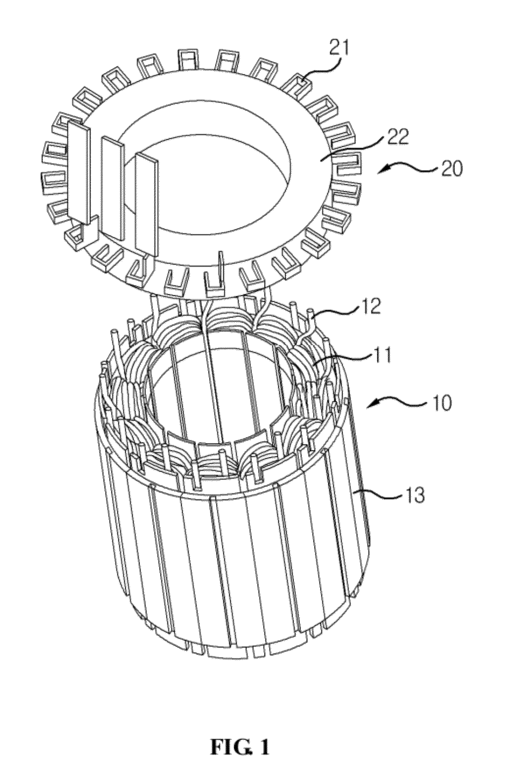
Meanwhile, a dielectric breakdown in a product among terminals may be generated to result in imperfection in motor operation and defect affecting safety of an operator, if a predetermined gap is not maintained among the terminals during insert molding operation.
Another problem is that the insert molding operation cannot be easily performed due to a tight gap among parts and materials of thin thickness.
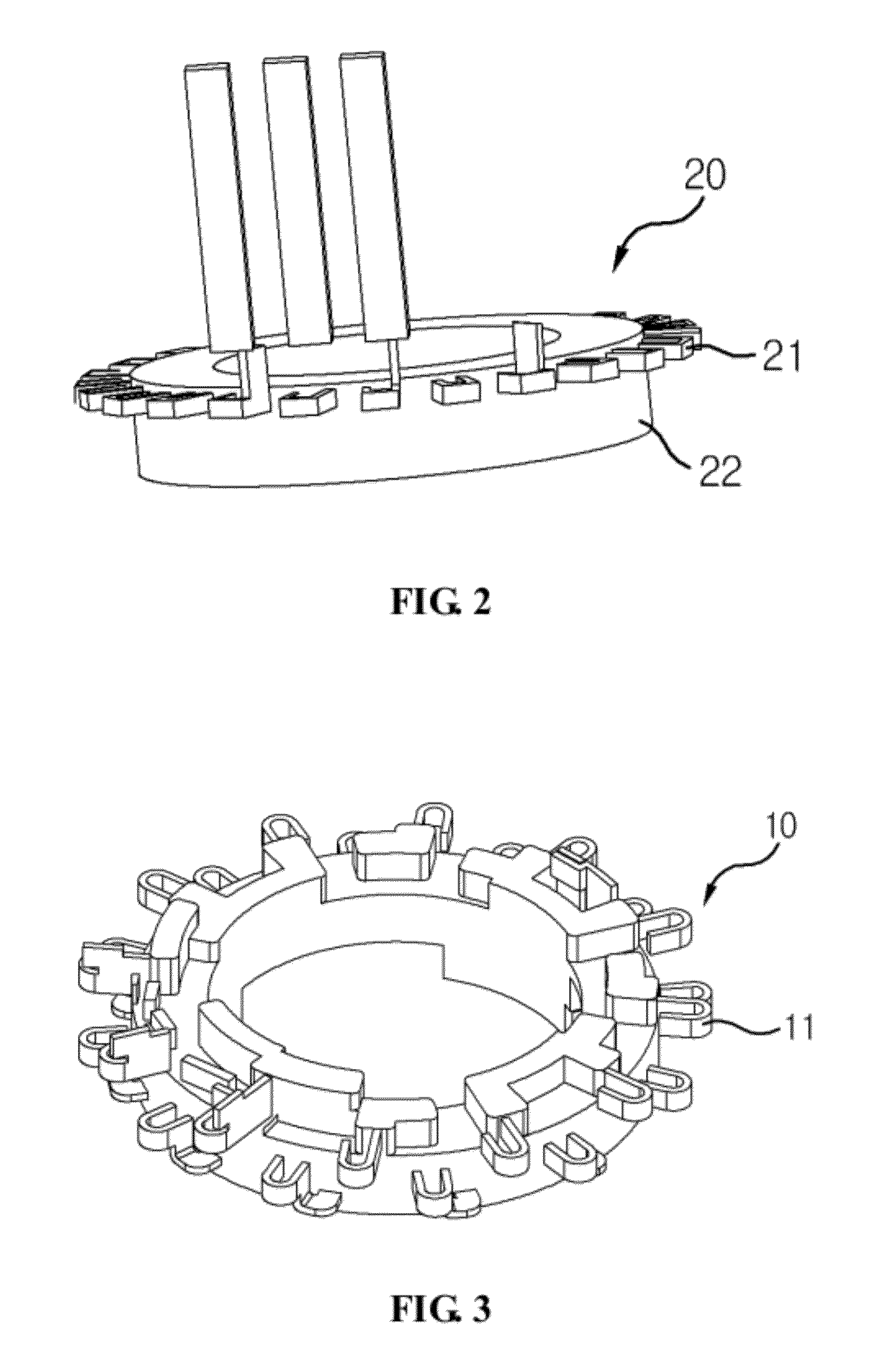
Still another problem is that a spatial restriction is generated during welding operation of coil terminals (21) due to the tight gap among terminals (21), if the terminals (21) are arranged in the above manner.
Still further problem is that an electrical insulation cannot be realized due to undesirable contact to welded portions among adjacent terminals (21) that is generated by the tight gap among terminals (21) in the welding operation.

Method used


Image

  • Bus bar of eps motor
  • Bus bar of eps motor
  • Bus bar of eps motor

Examples


Embodiment Construction

[0054]Advantages and features of the present invention may be understood more readily by reference to the following detailed description of exemplary embodiments and the accompanying drawings. Detailed descriptions of well-known functions, configurations or constructions are omitted for brevity and clarity so as not to obscure the description of the present disclosure with unnecessary detail. Thus, the present disclosure is not limited to the exemplary embodiments which will be described below, but may be implemented in other forms. In the drawings, the width, length, thickness, etc. of components may be exaggerated or reduced for the sake of convenience. Furthermore, throughout the descriptions, the same reference numerals will be assigned to the same elements in the explanations of the figures, and explanations that duplicate one another will be omitted.

[0055]Accordingly, the meaning of specific terms or words used in the specification and claims should not be limited to the liter...


PUM

PropertyMeasurementUnit
areaaaaaaaaaaa
circumferenceaaaaaaaaaa
torqueaaaaaaaaaa

Abstract

Disclosed is a bus bar of an EPS motor configured to improve a terminal structure of a bus bar to enable an easy assembly between a stator and the bus bar, whereby assemblage and operational reliability can be enhanced, the bus bar that is connected to a stator coil of the EPS motor, the bus bar including: an insulator made of insulation materials that forms a body of the bus bar; a lower terminal protrusively formed at a lower side of a periphery of the insulator, and connected to the stator coil; and an upper terminal protrusively formed at an upper side of the periphery of the insulator, and connected to the stator coil, whereby the terminals of the bus bar are divided to an upper terminal and a lower terminal to enhance assemblage and operational reliability by further obtaining a broader mutually discrete gap.

Description

CROSS-REFERENCE TO RELATED APPLICATIONS[0001]This application claims the benefit under 35 U.S.C. §119 of Korean Application Nos. 10-2010-0109896, filed Nov. 5, 2010, and 10-2010-0109900, filed Nov. 5, 2010, which are hereby incorporated by reference in their entirety.BACKGROUND OF THE DISCLOSURE[0002]1. Field of the Disclosure[0003]The present disclosure relates to a bus bar of an EPS motor, and more particularly to a bus bar of an EPS motor configured to improve a terminal structure of a bus bar to enable an easy assembly between a stator and the bus bar, whereby assemblage and operational reliability can be enhanced.[0004]The present disclosure further relates to a mold structure of a bus bar of an EPS motor, and more particularly to a mold structure of a bus bar of an EPS motor configured to fix position of a terminal in an insert molding process of bus bar by improving a terminal structure of the bus bar and to accurately maintain a mutual gap.[0005]2. Discussion of the Related ...

Claims


Application Information

Patent Timeline
Patent Type & Authority Applications(United States)
IPC IPC(8): H02K11/00B29C45/14
CPCB62D5/0403H02K2203/09H02K15/12H02K3/522H02K3/38H02K3/525
Inventor KIM, BYUNGYONG
Owner LG INNOTEK CO LTD
Why Eureka
Try Eureka