Rotor

Active Publication Date: 2012-05-10
DAIKIN IND LTD
View PDF0 Cites 10 Cited by
  • Summary
  • Abstract
  • Description
  • Claims
  • Application Information

AI Technical Summary

Benefits of technology

[0022]In the rotary electric machine, the rotor core has at least one magnetic barrier that is provided in each of the regions obtained by equally dividing the angle of the rotor core into ((N−1)×2) angles around the axis. Therefore, the magnetic barrier is provided near a position corresponding to a cycle of an (N−1)th harmonic component of a magnetic flux density that is supplied from the rotor to the stator (a fundamental wave is set to be a sine wave in which one cycle corresponds to one-round around the axis as the center). Thus, the (N−1)th harmonic component can be reduced in a relatively balanced manner. Since the (N−1)th harmonic component is caused by the whirling motion of the rotor, vibrations caused by the whirling motion of the rotor can be reduced.
[0023]In the fourth aspect of the rotor according to the present invention, the magnetic barrier is provided at the position corresponding to a cycle of the (2N+1)th harmonic component of the electromagnetic force. This can appropriately reduce the (2N+1)th harmonic component of the electromagnetic force. Alternatively, the magnetic barrier is provided at the position corresponding to the cycle of the (N±1)th harmonic components of the magnetic flux density. This can appropriately reduce the (N±1)th harmonic components of the magnetic flux density.
[0024]In th

Problems solved by technology

However, Japanese Patent Application Laid-Open No. 2005-52825 gives no consideration to a vibration caused by a whirling motion of the rotor, and canno

Method used


Image

  • Rotor
  • Rotor
  • Rotor

Examples


first embodiment

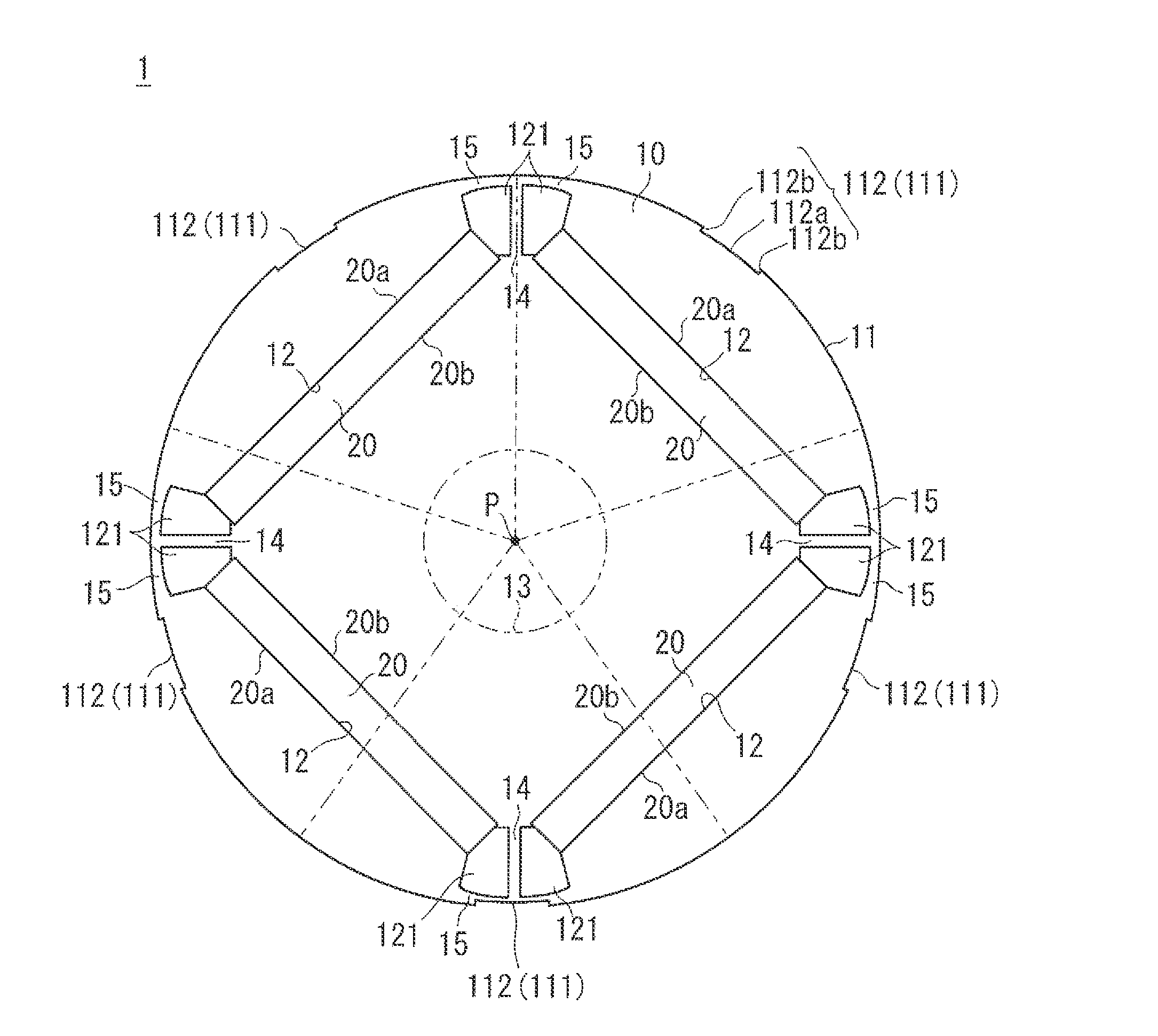
[0047]FIG. 1 shows a cross-section perpendicular to an axis P (which will be described later) of a rotor 1. As illustrated herein, the rotor 1 includes a rotor core 10 and a plurality of permanent magnets 20.

[0048]The plurality of permanent magnets 20 are, for example, rare-earth magnets (such as rare-earth magnets containing neodymium, iron, boron, as a main component), and arranged annularly around the predetermined axis P. In an example shown in FIG. 1, each of the permanent magnets 20 is shaped into a rectangular parallelepiped plate. Each of the permanent magnets 20 is arranged in such a position that, at the center thereof with respect to a direction of a circumference (hereinafter simply referred to as a circumferential direction) whose center is placed at the axis P, a thickness direction thereof can be coincident with a direction of a diameter (hereinafter simply referred to as a diameter direction) whose center is placed at the axis P. Here, it is not always necessary that...

second embodiment

[0087]A rotor 1 illustrated in FIG. 9 is different from the rotor 1 illustrated in FIG. 1 in terms of the number of the magnetic barriers 111.

[0088]In an example shown in FIG. 9, at least one of the magnetic barriers 111 is provided in each of regions obtained by equally dividing the rotor core 10 into ((p+1)×2) in angle around the axis P (in the example shown in FIG. 9, the groove portions 112). In FIG. 9, an example of such regions are shown as regions each sandwiched between adjacent two of the alternate long and two short dashes lines extending radially from the axis P as the center.

[0089]As described in the first embodiment above, referring to the expression (3), the p-th harmonic component of the magnetic flux density B2 is caused by the rotating motion of the rotor 1, and is a component that contributes to a torque of a rotary electric machine and does not cause an increase of vibrations. The other harmonic components are components that can be a factor for an electromagnetic...

third embodiment

[0100]Rotors 1 shown in FIGS. 13 and 14 is different from the rotors 1 shown in FIGS. 1 and 9, in terms of the configuration of the magnetic barrier 111.

[0101]The magnetic barriers 111 are shown as holes 113. A fluid, such as air or a cooling medium, is loaded within the holes 113. Thus, the holes 113 can function as magnetic barriers. The holes 113 are provided between the outer circumferential side surface 11 of the rotor core 10 and the permanent magnet 20 (and more specifically, between a circular ring passing through the permanent magnet 20 and the outer circumferential side surface 11). The magnetic barrier 111 is not limited to the hole 113, and the hole 113 being loaded with a non-magnetic material may be adoptable. If a non-magnetic material is loaded, the strength of the rotor 1 can be improved.

[0102]In the examples shown in FIGS. 13 and 14, the magnetic barrier 111 (hole 113) has an elongated shape when seen in the axial direction, and is arranged with the long side there...


PUM


Abstract

A rotor includes a plurality of permanent magnets arranged annularly around an axis and a rotor core. The rotor core includes 2N (where N is a natural number) magnetic pole faces and a plurality of magnetic barriers. The 2N magnetic pole faces produce, due to the plurality of permanent magnets, magnetic poles in a radial direction in such a manner that different polarities can be alternately produced around the axis. The magnetic barriers are provided at a side close to the magnetic pole faces relative to the permanent magnets. At least one of the magnetic barriers is provided in each region obtained by equally dividing the rotor core into (2N+1), ((N+1)×2) or ((N−1)×2) angles around the axis.

Description

CROSS-REFERENCE TO RELATED APPLICATIONS[0001]This national phase application claims priority to Japanese Patent Application Nos. 2009-172013 filed on Jul. 23, 2009 and 2009-198315 filed on Aug. 28, 2009. The entire disclosure of Japanese Patent Application Nos. 2009-172013 and 2009-198315 is hereby incorporated herein by reference.TECHNICAL FIELD[0002]The present invention relates to a rotor, and particularly to a shape of a rotor core.BACKGROUND ART[0003]Japanese Patent Application Laid-Open No. 2005-52825 discloses a rotor in which a cogging torque is reduced and additionally a harmonic content in an induced voltage is reduced to thereby reduce a vibration and a noise. The rotor includes a rotor core and a plurality of permanent magnets. The plurality of permanent magnets is arranged annularly around a rotation axis. The plurality of permanent magnets is embedded in the rotor core. The diameter of an outer circumferential side surface of the rotor core decreases at both ends of th...

Claims


Application Information

Patent Timeline
IPC IPC(8): H02K1/27
CPCH02K1/276H02K29/03H02K1/2766H02K1/27
Inventor ARAKI, SHINTAROUYAMAGIWA, AKIO
Owner DAIKIN IND LTD
Why Eureka
Try Eureka