Supercharge Your Innovation With Domain-Expert AI Agents!

Server cabinet structure

a server cabinet and structure technology, applied in the field of server cabinets, can solve the problems of easy loss of screws, high cost of thumb screws, difficult screw alignment, etc., and achieve the effect of reducing the time required for loading and unloading operations, facilitating the procedure of loading and unloading the tray, and achieving the highest operation performan

Inactive Publication Date: 2012-05-10
INVENTEC CORP
View PDF10 Cites 8 Cited by
  • Summary
  • Abstract
  • Description
  • Claims
  • Application Information

AI Technical Summary

Benefits of technology

[0013]Beneficial effects of the present invention are as follows. The fixing component is fixed in the frame bar by insertion, so that the tray can be fixedly disposed into the rack or removed from the rack quickly and conveniently, which not only greatly simplifies the procedures for loading and unloading the tray, but also reduces the time required for the loading and unloading operations.
[0014]Additionally, the guide rails of the rack are completely accommodated in the recessed portions of the tray, and do not occupy any other usable room inside the rack, so that the rack can be loaded with the maximum number of circuit boards, and a single server cabinet can achieve the highest operation performance.

Problems solved by technology

Therefore, the fixation achieved by screwing the screw into the screw hole makes it inconvenient to plug in and pull out the main board of the server, and also leads to problems that the alignment of the screws is not easy, the screws are easily lost, and the thumb screw is expensive.
Thus, the slide rail brackets and slide rails occupy too much room inside the server rack, which limits the usable room in the server rack.
Therefore, the number of circuit boards that can be loaded in a single server rack is also limited, and installation of the maximum number of circuit boards cannot be achieved, so that the operation performance of the server cabinet cannot be improved.

Method used


Image

  • Server cabinet structure
  • Server cabinet structure
  • Server cabinet structure

Examples


Embodiment Construction

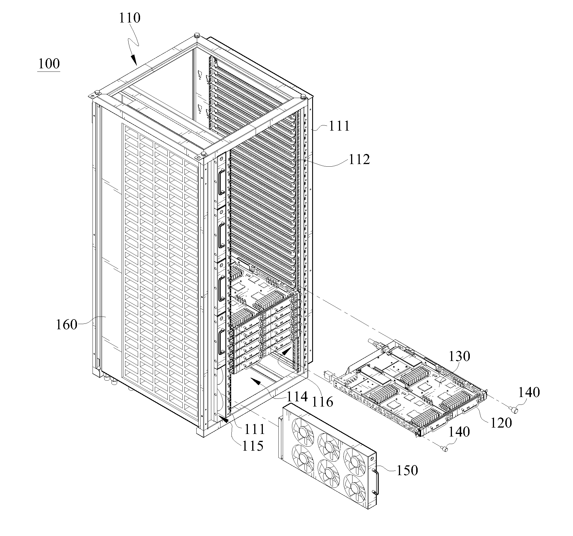
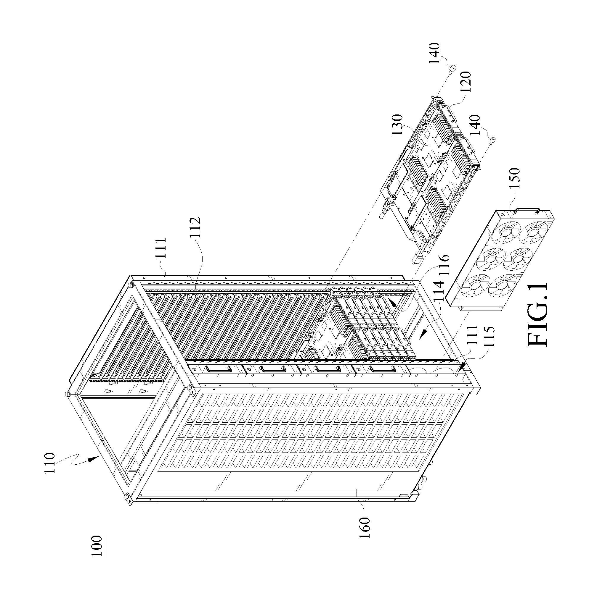
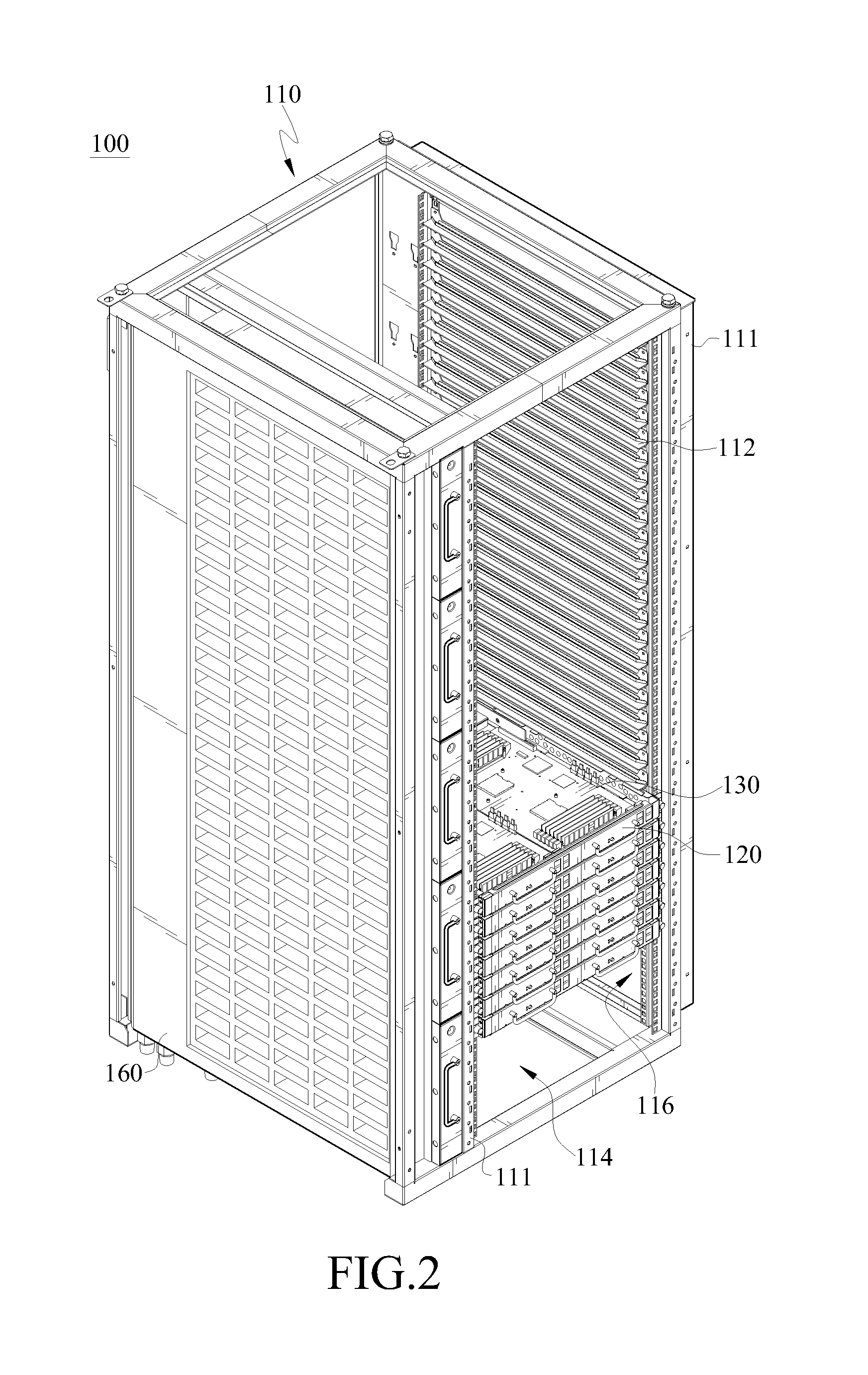
[0025]FIGS. 1 and 2 are schematic three-dimensional views according to an embodiment of the present invention. As shown in the FIGS. 1 and 2, a server cabinet 100 of the present invention comprises a rack 110, a tray 120, at least one circuit board 130, at least one fixing component 140 and at least one fan module 150. The rack 110 is a hollow rack constituted by multiple steel bars, steel plates and angle steel, so as to form an accommodation room inside the rack 110. Two opposite side surfaces of the rack 110 respectively have two opposite frame bars 111 and at least two guide rails 112. Two opposite side surfaces of the rack 110 are hollowed out to form large-area air inlets / outlets for an airflow of the fan module 150. In addition, one side of the rack 110 is opened with an opening 114, and the opening 114 is in communication with the accommodation room, so that the inside of the rack 110 is in communication with the outside through the opening 114.

[0026]The guide rails 112 of t...


PUM


Abstract

A server cabinet structure includes a rack, at least one tray and at least one fixing component. The rack has two opposite frame bars and at least two guide rails correspondingly disposed on the frame bars. The tray is disposed on the two guide rails, and is capable of sliding into the rack. The guide rails are accommodated in recessed portions of the tray exactly. The tray presses against the frame bars through a stop plate. One combining hole of the stop plate is corresponding to an assembly hole of the frame bar. The fixing component passes through the combining hole and the assembly hole, and is inserted into the frame bar, so as to limit and keep the tray inside the rack.

Description

CROSS-REFERENCE TO RELATED APPLICATIONS[0001]This non-provisional application claims priority under 35 U.S.C. §119(a) on Patent Application No(s). 099138222 filed in Taiwan, R.O.C. on Nov. 5, 2010, the entire contents of which are hereby incorporated by reference.BACKGROUND OF THE INVENTION[0002]1. Field of the Invention[0003]The present invention relates to a server cabinet, and more particularly to a server cabinet structure to and from which a tray can be loaded and unloaded quickly.[0004]2. Related Art[0005]With the development of science and technology, a computer device is expected to start and run various programs within a shortest period, so as to meet speed requirements of data processing from customers. Development objects of increasing processing speed and performing multiplex operation are achieved by increasing chip precision in the industry, so that server architecture consisting of multiple circuit boards and electronic components thereof is developed.[0006]When multi...

Claims


Application Information

Patent Timeline
Patent Type & Authority Applications(United States)
IPC IPC(8): H05K5/02
CPCH05K7/1489
Inventor CHEN, CHIEN-ANTUNG, KAI-YANGSHIH, MING-HUNGYANG, CHUN-YINGNI, CHUNG-SHENG
Owner INVENTEC CORP
Features
  • R&D
  • Intellectual Property
  • Life Sciences
  • Materials
  • Tech Scout
  • Unparalleled Data Quality
  • Higher Quality Content
  • 60% Fewer Hallucinations
Learn More