
Double microstrip transmission line having common defected ground structure and wireless circuit apparatus using the same

Active Publication Date: 2012-05-10
SOONCHUNYANG UNIV IND ACAD COOP FOUND
View PDF4 Cites 22 Cited by
  • Summary
  • Abstract
  • Description
  • Claims
  • Application Information

AI Technical Summary

Benefits of technology

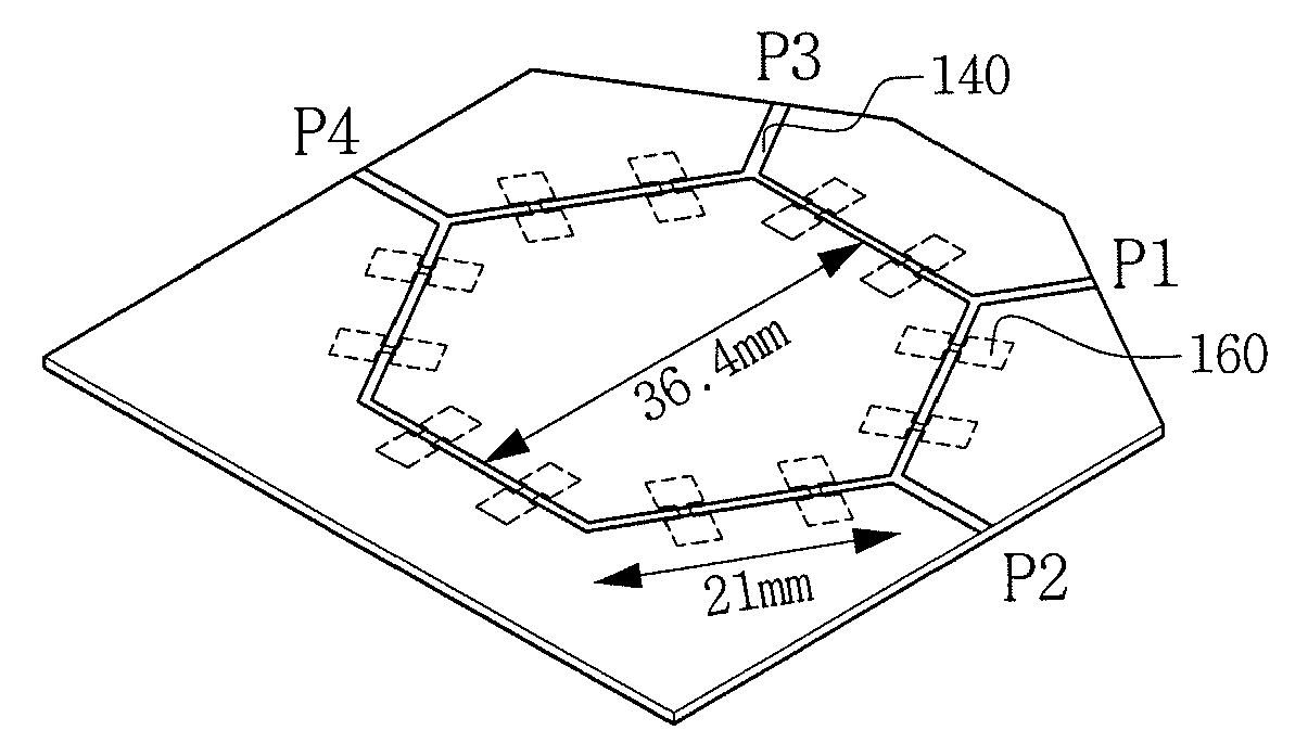
[0009]The present disclosure is directed to providing a microstrip transmission line with a novel structure, which may improve the degree of integration by minimizing the length of the microstrip transmission line in a circuit design, and significantly reducing the sizes of various wireless circuits using the structure of the microstrip transmission line.

Problems solved by technology

However, although the defected ground structure (DGS) is inserted into the ground surface, since there is a limitation in reducing the length of the microstrip transmission line while maintaining desired electrical performance, it is difficult to improve the degree of integration by minimizing the length of the microstrip transmission line or reducing the size of the wireless circuit without performance deterioration.

Method used


Image

  • Double microstrip transmission line having common defected ground structure and wireless circuit apparatus using the same
  • Double microstrip transmission line having common defected ground structure and wireless circuit apparatus using the same
  • Double microstrip transmission line having common defected ground structure and wireless circuit apparatus using the same

Examples


Embodiment Construction

[0023]Exemplary embodiments now will be described more fully hereinafter with reference to the accompanying drawings, in which exemplary embodiments are shown. The present disclosure may, however, be embodied in many different forms and should not be construed as limited to the exemplary embodiments set forth therein. Rather, these exemplary embodiments are provided so that the present disclosure will be thorough and complete, and will fully convey the scope of the present disclosure to those skilled in the art. In the description, details of well-known features and techniques may be omitted to avoid unnecessarily obscuring the presented embodiments.

[0024]The terminology used herein is for the purpose of describing particular embodiments only and is not intended to be limiting of the present disclosure. As used herein, the singular forms “a”, “an” and “the” are intended to include the plural forms as well, unless the context clearly indicates otherwise. Furthermore, the use of the t...


PUM


Abstract

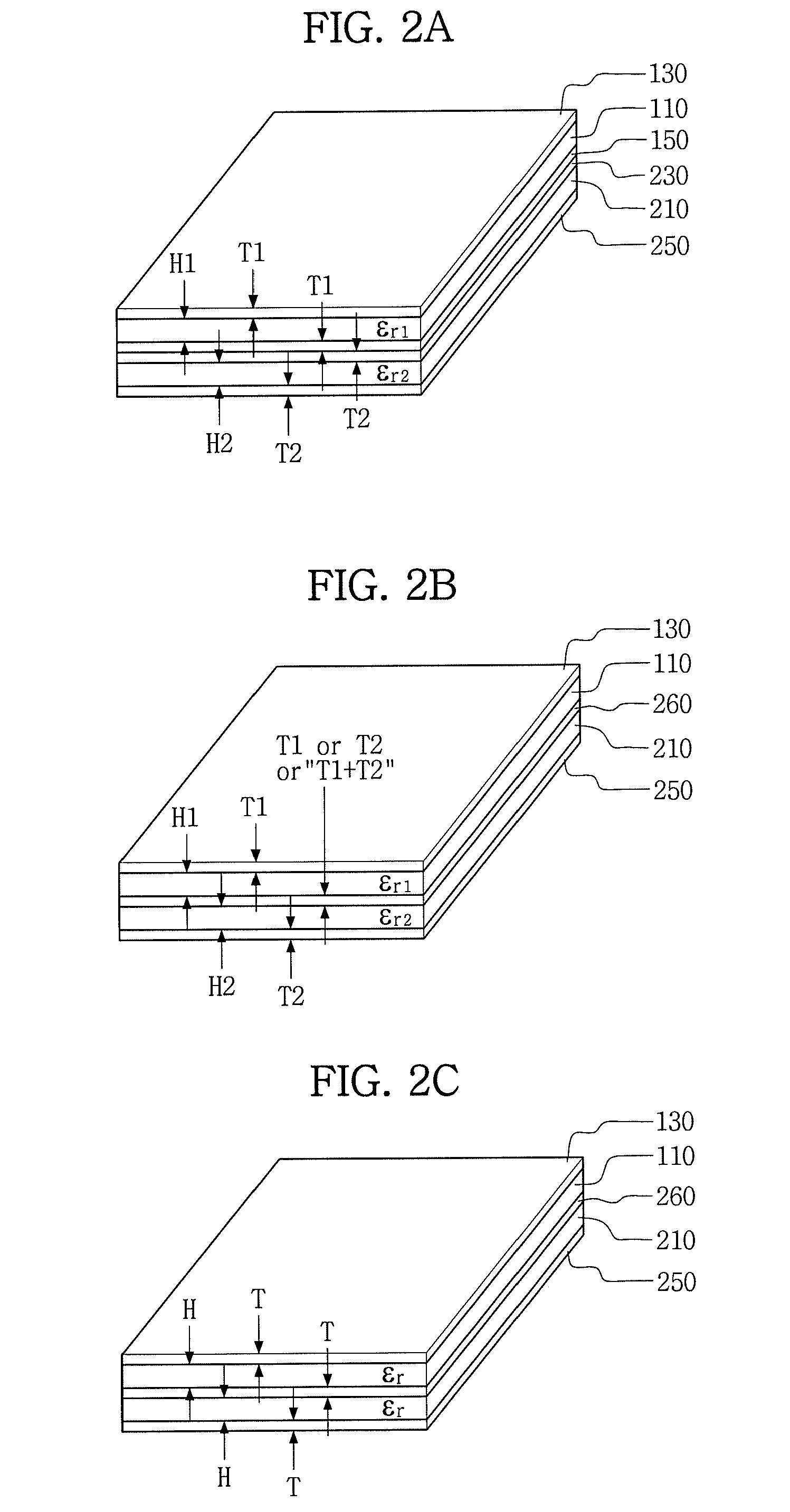
Disclosed are a microstrip transmission line having a common defected ground structure (DGS) and a wireless circuit apparatus having the same. The microstrip transmission line realizes a common defected ground structure (DGS) and a double microstrip structure, and includes: a first dielectric layer; a first signal line pattern formed on a first surface of the first dielectric layer; a common ground conductive layer formed on a second surface of the first dielectric layer and having a defected ground structure, the first surface facing the second surface; a second dielectric layer having a first surface brought into contact with the common ground conductive layer, and facing the first dielectric layer while interposing the common ground conductive layer between the first dielectric layer and the second dielectric layer; and a second signal line pattern formed on a second surface of the second dielectric layer, the first surface facing the second surface.

Description

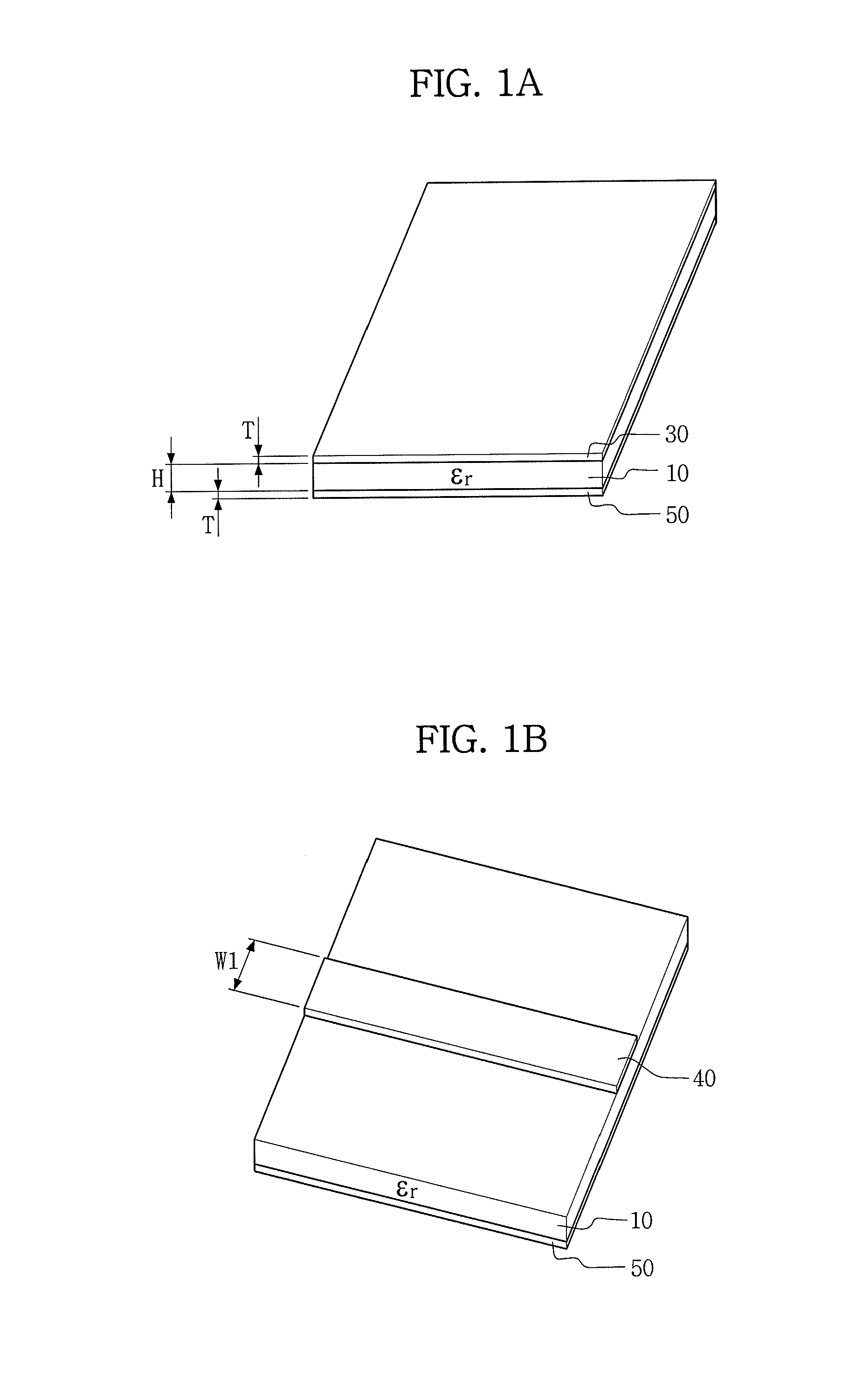
CROSS-REFERENCE TO RELATED APPLICATION[0001]This application claims priority to Korean Patent Application No. 10-2010-0111367, filed on Nov. 10, 2010, and all the benefits accruing therefrom under 35 U.S.C. §119, the contents of which in its entirety are herein incorporated by reference.BACKGROUND[0002]1. Field[0003]The present disclosure relates to a microstrip transmission line, and more particularly, to a microstrip transmission line having a common defected ground structure and a wireless circuit apparatus having the same.[0004]2. Description of the Related Art[0005]A representative transmission line structure, which is widely used for forming circuits and parts for wireless communication of a radio frequency (RF) and microwave band, is a microstrip transmission line. The microstrip transmission line is manufactured from a printed circuit board (PCB) as illustrated in FIG. 1a and has a planar structure. The structure of the printed circuit board as illustrated in FIG. 1a is well...

Claims


Application Information

Patent Timeline
IPC IPC(8): H01P3/08
CPCH01P1/2039H01P3/081H01P3/082H01P3/088H01P5/184H01P5/185H01P5/028H01P5/16
Inventor LIM, JONGSIKAHN, DAL
Owner SOONCHUNYANG UNIV IND ACAD COOP FOUND
Learn More