Eureka AIR delivers breakthrough ideas for toughest innovation challenges, trusted by R&D personnel around the world.

System and Method for Tracking, Monitoring and Deriving the Location of Transient Objects by Monitoring the Location of Equipment Used to Move the Objects

a technology for transient objects and equipment, applied in the field of tracking, monitoring and locating transient objects, can solve the problems of innate weaknesses of manual entry, system inability to tell where on the dock the shipment is, and inability to know if an item or component is on the dock

Inactive Publication Date: 2012-05-10
HAMMEL
View PDF11 Cites 72 Cited by
  • Summary
  • Abstract
  • Description
  • Claims
  • Application Information

AI Technical Summary

Benefits of technology

"The patent describes a system that combines a Real-Time Location System (RTLS) with a Dangerous Asset Management System (DAMS) to track the location and movement of objects in real-time. The RTLS uses wireless transmitters attached to objects to track their movement. The system can be used in various settings such as in shipment components or equipment used in construction. By monitoring the movement of the equipment, the system can identify the location of the object being acted upon and track its movement. This helps ensure the object is always in the correct place. The system can also store the location of the object for future reference. Overall, the system provides automated accuracy in identifying the location of objects and the people or equipment acting on them."

Problems solved by technology

However, with just that much information, the DA system cannot tell where on the dock the shipment is while it is still on the dock.
It can't know if an item or component is in transit from a door to another door, or where it is stored if it needs to be stored for a period of time before being loaded on a trailer.
However, there are innate weaknesses with manual entry.
Regarding accuracy, manual data entry can be prone to errors.
It could be difficult, if not impossible, for the DA system to detect such an error and, therefore, the incorrect data will be allowed to propagate throughout the DA system.
Manual keying data takes time, and requires the user to look at the device as opposed to looking at their surroundings.
Scanning can add two types of inefficiency.
First, it is unlikely that the location ID tag will be exactly where the component is placed.
Bays are by nature open spaces away from pillars and walls, and therefore do not have convenient places to put a scanable location ID tag.
Utilizing ceiling mounted hanging barcode signs would require the use of expensive long range scanners, and the signs themselves could interfere with or be blocked by tall or stacked shipments or components.
This adds a previously unneeded stop to perform the scan, extra travel time to get from the tag to the actual location, and possibly an extra direction change of the vehicle or equipment performing the move.
All this represents time loss and equipment wear.
Yet another drawback is that there is always the chance that a user could accidentally scan the wrong barcode for a move.
The user may inadvertently scan the barcode for the door instead of the barcode for the bay when the shipment is picked up for loading into a trailer.
The DA system typically will not have any checks preventing this, as the door would be just as valid for a destination as the bay, but the error would make the trailer manifest incorrect.
There are various drawbacks to applying an RFID tag to each shipment.
The cost of tagging all items is expensive, from both an equipment and labor cost standpoint.
Since the tags will be placed on various kinds of materials, there is a challenge in obtaining acceptable read rates for all of the various kinds of materials.

Method used


Image

  • System and Method for Tracking, Monitoring and Deriving the Location of Transient Objects by Monitoring the Location of Equipment Used to Move the Objects
  • System and Method for Tracking, Monitoring and Deriving the Location of Transient Objects by Monitoring the Location of Equipment Used to Move the Objects
  • System and Method for Tracking, Monitoring and Deriving the Location of Transient Objects by Monitoring the Location of Equipment Used to Move the Objects

Examples


Embodiment Construction

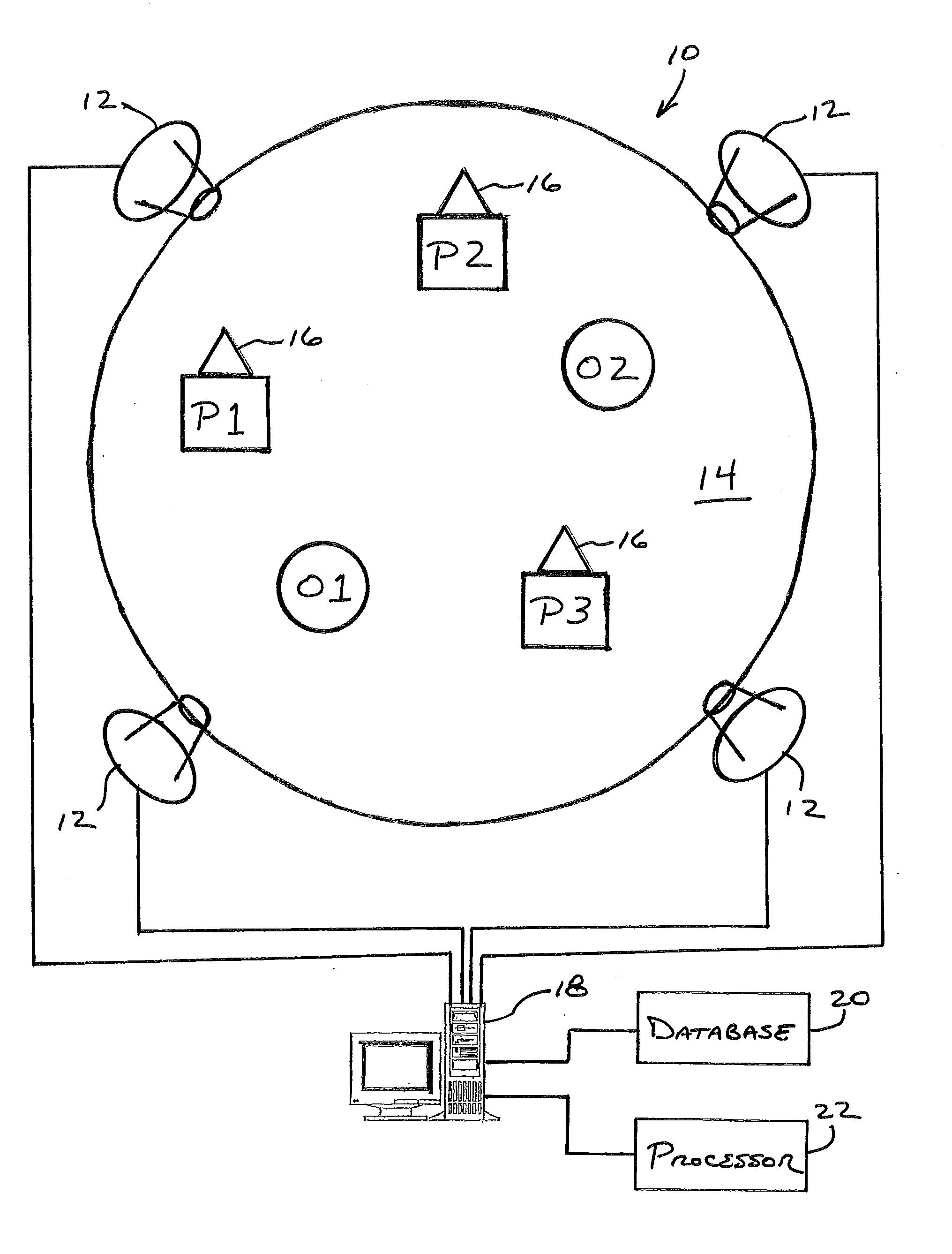
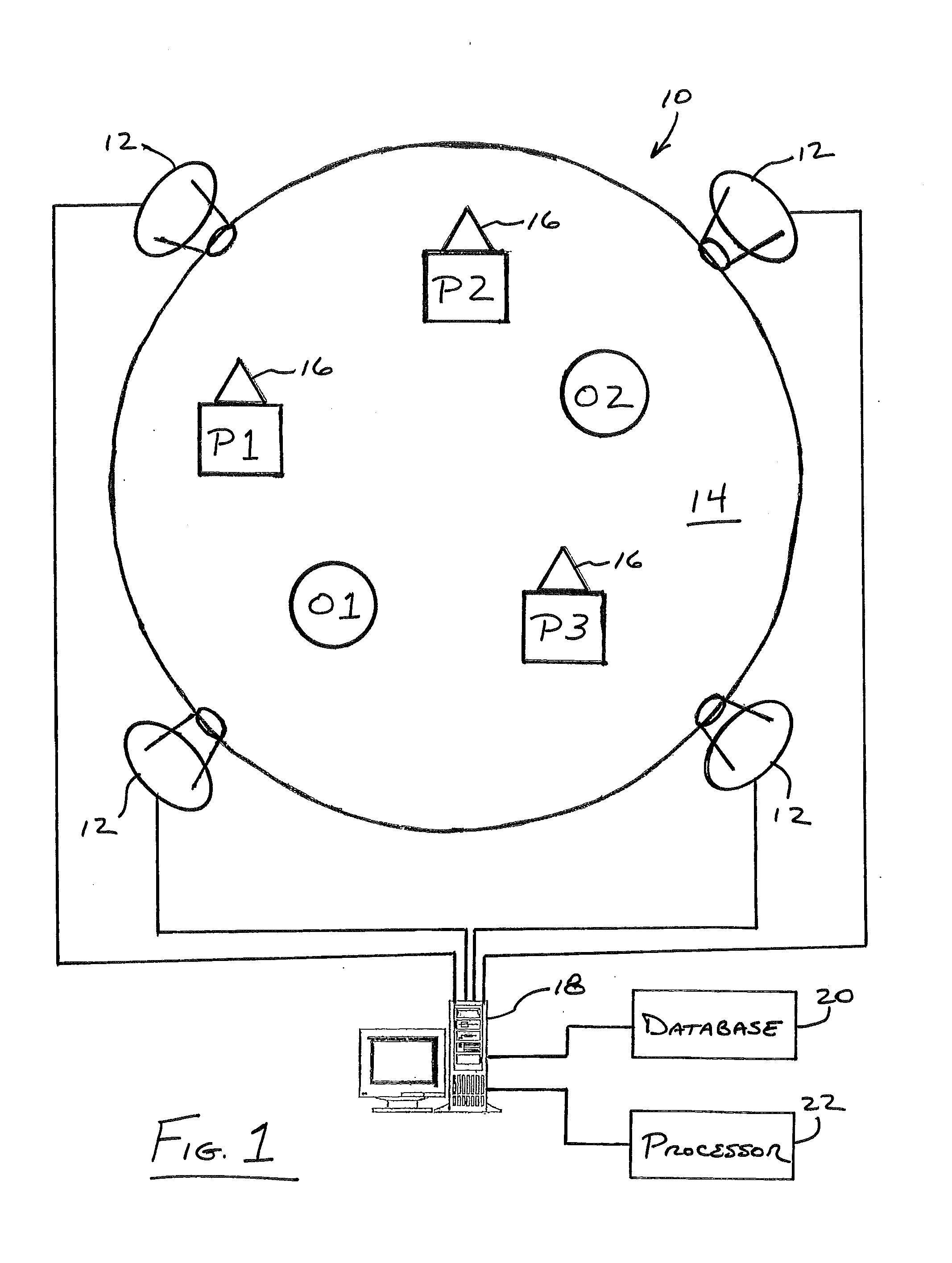
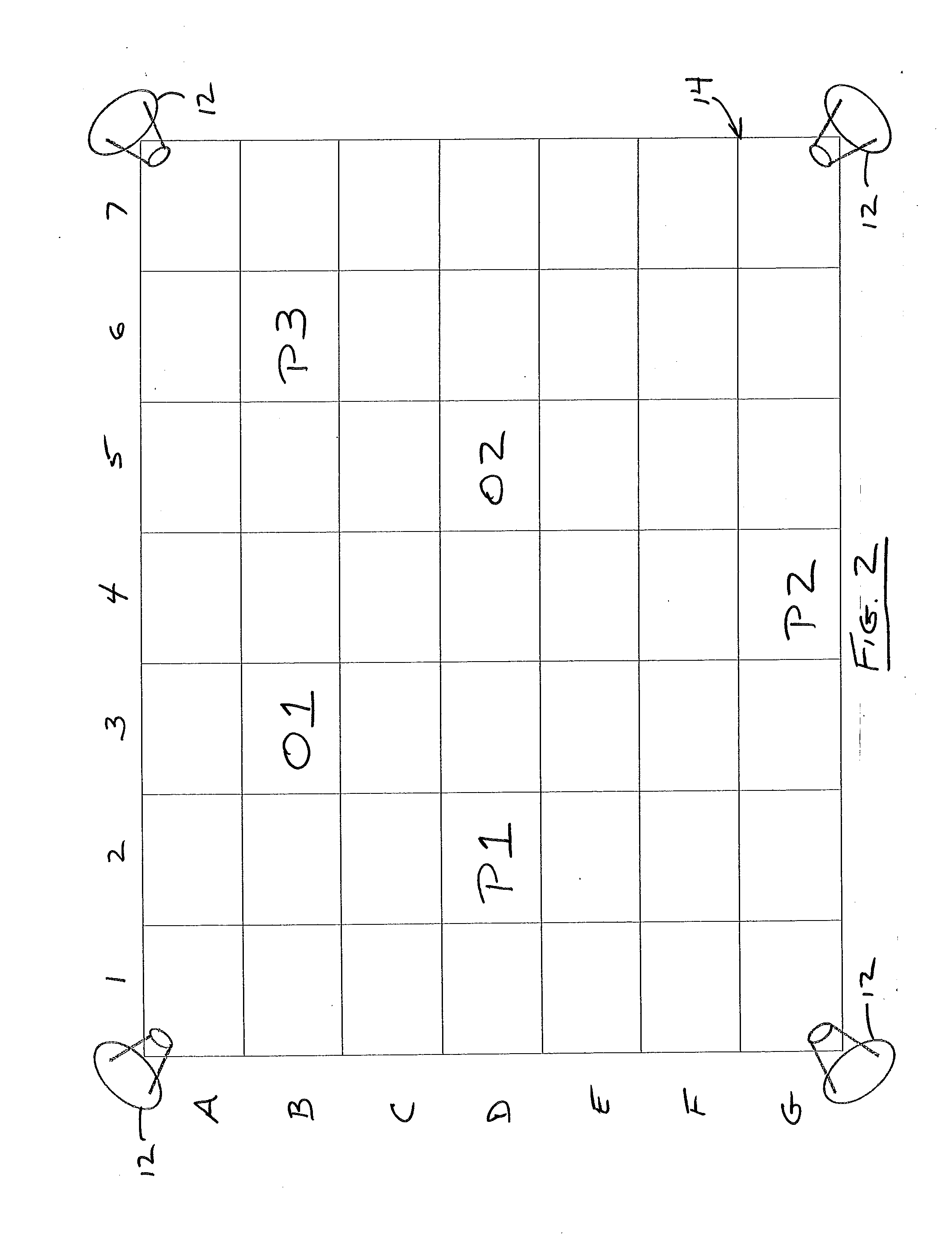
[0029]Referring to FIG. 1, a system for tracking, monitoring and deriving the location of transient objects is shown generally at 10. The system 10 includes a plurality of receivers or readers 12 placed about a predefined area 14 to be monitored. As used herein, the terms receiver and reader are used to denote the same or similar device. The predefined area 14 may be any area where transient objects are stored and their location needs to be monitored, such as, for example, a dock, a bay, a warehouse, etc. The receivers 14 should be placed such that they provide coverage for the area 14 to be monitored. While four receivers 12 are shown in FIGS. 1 and 2, any number may be implemented in accordance with the present invention.

[0030]Within the area 14 to be monitored, there are a number of objects O1, O2 which are to be moved and stored within the area 14. Pieces of equipment P1, P2, P3 are used to move the objects O1, O2 within the area 14. The pieces of equipment P1, P2, P3 may be mot...


PUM


Abstract

System and method combining a Dock Automation (“DA”) system with a Real Time Locating System (“RTLS”) to achieve automated accuracy relating to the location of shipment components. An RTLS system is used to track the position of assets which move shipment components over time. When any action is performed on a shipment component in the DA system, the time of the action and the RTLS device ID of the asset (piece of equipment or person) performing the action would be used in conjunction with the RTLS database, providing the location at which the event took place. Knowing the location of the asset performing an action on a component implies knowing the location of the component being acted upon. At any time, the component should be wherever the last asset interacted with it.

Description

FIELD OF THE INVENTION[0001]The present invention is directed toward tracking, monitoring and locating transient objects such as, for example, shipment components and, more particularly, toward a system and method for tracking, monitoring and locating transient objects by monitoring the location of equipment used to move the objects.BACKGROUND OF THE INVENTION[0002]A Dock Automation system (“DA system”) generally refers to a collection of software and hardware components employed to track and manage vehicles, trailers, trailer contents, etc. as they approach and depart a dock, as well as assign and / or record the work of moving of transient items (typically shipments, which in turn are made up of components) across the dock space or area from trailer to trailer.[0003]For example, as a trailer is placed at an unload door, it is entered into the DA system as ready to unload. As items are removed from the trailer, they are scanned so the DA system knows they are unloaded from the traile...

Claims


Application Information

Patent Timeline
Patent Type & Authority Applications(United States)
IPC IPC(8): G08B1/08
CPCG06K17/00G06Q10/08G06K2017/0045
Inventor NAGY, VINCENT I.
Owner HAMMEL
Why Eureka
Eureka Blog
Learn More