Backlight module
- Summary
- Abstract
- Description
- Claims
- Application Information
AI Technical Summary
Benefits of technology
Problems solved by technology
Method used
Image
Examples
first embodiment
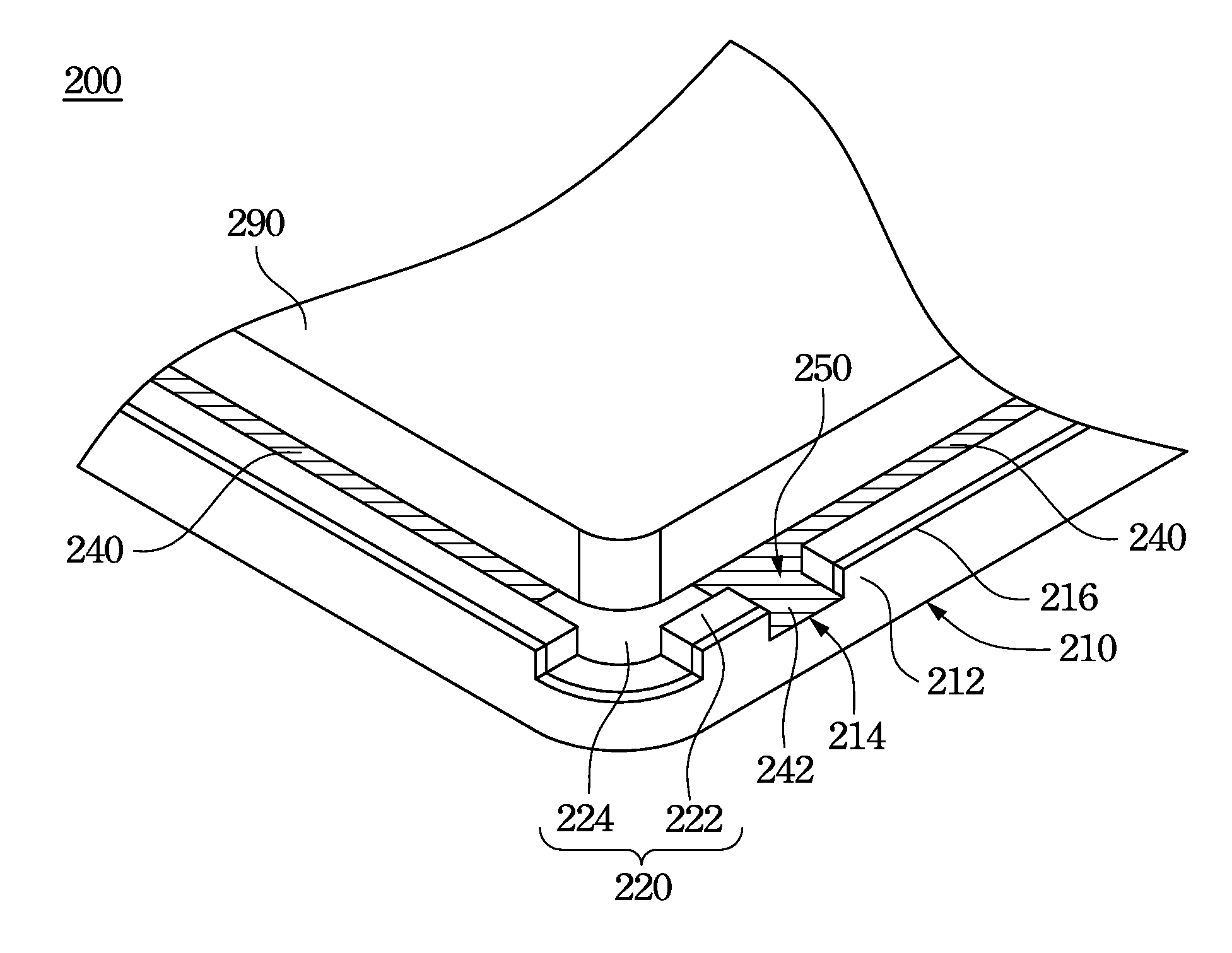
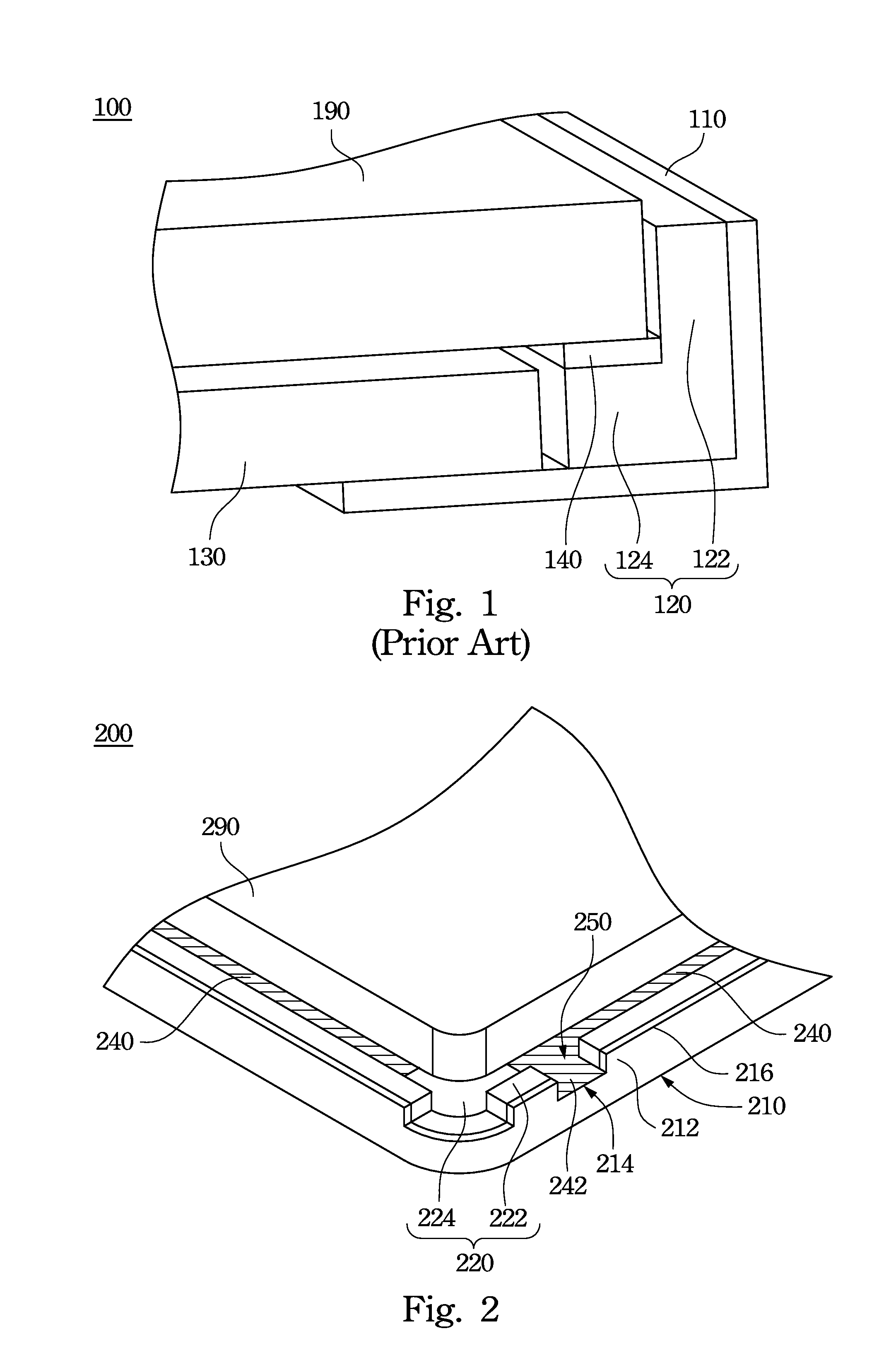
[0023]FIG. 2 is an oblique diagram of the backlight module of the invention. The backlight module 200 includes an outer frame 210, and inner frame 220 and an adhesive device 240. The outer frame 210 has a sidewall 212, and a hole 214 formed on the sidewall 212. The inner frame 220 is disposed inside of the outer frame 210. The inner frame 220 includes a block wall 222 and a support 224. The block wall 222 has an inner surface, an outer surface. The support 224 is disposed on the inner surface of the block wall 222, and the outer surface of the block wall 222 is in contact with the outer frame 210. A liquid crystal display panel 290 is disposed on the support 224 and is positioned by the block wall 222. The adhesive device 240 is disposed between the support 224 and the liquid crystal display panel 290. The adhesive device 240 adheres to the support 224 and the liquid crystal display panel 290 respectively, so that the liquid crystal display panel 290 is positioned on the support 224...
second embodiment
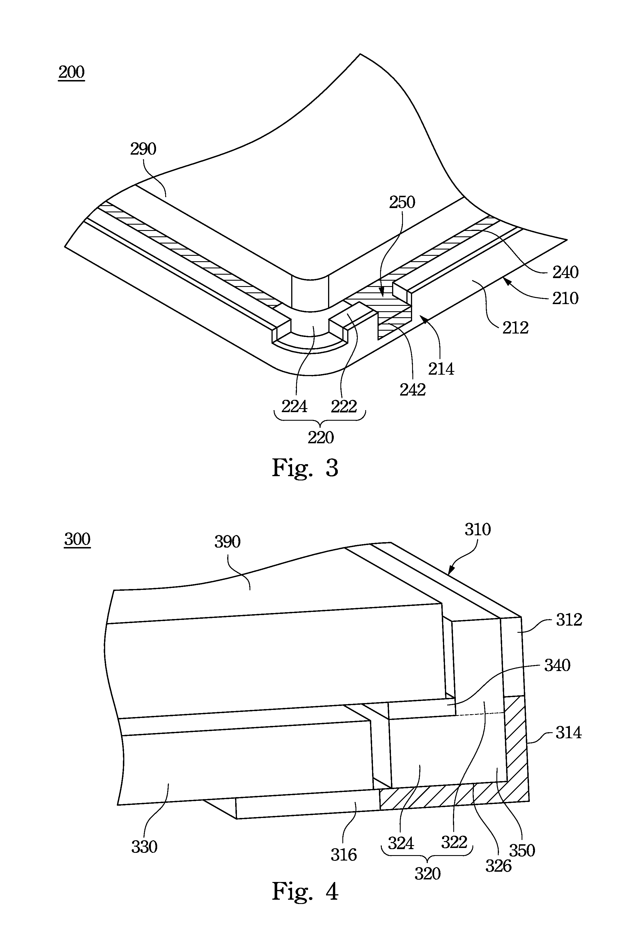
[0026]FIG. 3 is a schematic diagram of the backlight module of the invention. The backlight module 200 includes the outer frame 210, the inner frame 220, and the adhesive device 240. The hole 214 is formed on the sidewall 212 of the outer frame 210. The rework section 250 formed on the inner frame 220 is the opening. The liquid crystal display panel 290 is disposed on the support 224 and is positioned by the block wall 222. The adhesive device 240 is disposed on the support 224 to fasten the liquid crystal display panel 290 on the support 224. The extending portion 242 of the adhesive device 242 inserts to the opening of the rework section 250. In one or some embodiments, the extending portion 242 is extended over the hole 214 and is stuck on the outer surface of the sidewall 212. In other words, the extending portion 242 is extended through the hole 214 to exceed the outer surface of the sidewall 212, referred to FIG. 3. The extending portion 242 exposed to the outer surface of the...
third embodiment
[0028]FIG. 4 is a sectional diagram of the backlight module of the invention. The backlight module 300 includes the outer frame 310, the inner frame 320, and the adhesive device 340. The outer frame 310 has the sidewall 312 and a bottom plate 316, wherein the bottom plate 316 is connected to the sidewall 312 vertically. The outer frame 310 has the hole 314, and the hole 314 is formed on the sidewall 312 and the bottom plate 316. The hole 314 formed on the sidewall 314 further penetrates the bottom plate 316. The inner frame 320 has the block wall 322 and the support 324. The liquid crystal display panel 390 is disposed on the support 324 and is positioned by the block wall 322. The adhesive device 340 is disposed on the support 324 to fasten the liquid crystal display panel 390 on the support 324. The inner frame 320 has the rework section 350. The inner frame 320 has a bottom portion 326 disposed above the bottom plate 316. The rework section 350 is disposed corresponding to the ho...
PUM
 Abstract
Description
Claims
Application Information
 - R&D
- Intellectual Property
- Life Sciences
- Materials
- Tech Scout
- Unparalleled Data Quality
- Higher Quality Content
- 60% Fewer Hallucinations
Browse by: Latest US Patents, China's latest patents, Technical Efficacy Thesaurus, Application Domain, Technology Topic, Popular Technical Reports.
© 2025 PatSnap. All rights reserved.Legal|Privacy policy|Modern Slavery Act Transparency Statement|Sitemap|About US| Contact US: help@patsnap.com


