Using multi-level pulse width modulated signal for real time noise cancellation

a multi-level pulse width and modulation technology, applied in pulse techniques, instruments, code conversion, etc., can solve problems such as high sensitivity, aliasing and quantization noise in systems, and low dynamic rang

Inactive Publication Date: 2012-05-10
MAXIM INTEGRATED PROD INC
View PDF3 Cites 13 Cited by
  • Summary
  • Abstract
  • Description
  • Claims
  • Application Information

AI Technical Summary

Benefits of technology

[0007]Embodiments of a mixed signal processing circuit include an analog to PWM converting circuit and a finite impulse response (FIR) filter. The FIR filter includes a multiple output tapped delay line and a summing and integration circuit. The mixed signal processing circuit is configured for converting an input analog signal to a PWM signal, forming a multi-level PWM signal from the PWM signal and one or more delayed versions of the PWM signal, and converting the multi-level PWM signal to an output analog signal. In some embodiments, the analog to PWM converting circuit is implemented using a triangle waveform generator and a comparator. In some embodiments, the FIR filter is implement using a PWM delay line and a resistive network to apply scaling coefficients of the FIR filter. The mixed signal processing circuit can be implemented within a noise cancellation headphone to generate a noise cancelling signal. In general, the mixed signal processing circuit can be used in applications that would be benefitted from the combination of analog input/output and digital filter techniques.
[0008]In one aspect, a signal processing circuit is disclosed. The signal processing circuit includes a converting circuit configured to receive an input analog signal and to output a pulse width modulated signal corresponding to the analog signal; a delay line coupled to the converting circuit to receive the pulse width modulated signal, wherein the delay line comprises one or more delay line taps, each delay line tap configured to output a delayed version of the pulse width modulated signal; a scaling circuit coupled to the converting circuit and to the one or more delay line taps, where the scaling circuit is configured to scale the pulse width modulated signal and each of the one or more delayed versions of the pulse width modulated signal, thereby forming multiple scaled pulse width modulated signals; and a summing and integration circuit coupled to the scaling circuit, wherein the summing and integration circuit is configured to receive the multiple scaled pulse width modulated signals, to sum the multiple scaled pulse width modulated signals into a multiple-level pulse width modulated signal, and to convert the multiple-level pulse width modulated signal to an output analog signal.
[0009]In some embodiments, the converting circuit comprises a comparator and a triangle waveform generator, wherein the comparator is configured to compare the input analog signal and a triangle waveform received from the triangle waveform generator, and to output the pulse width modulated signal in response to the comparison. In some embodiments, a period of the pulse width modulated signal corresponds to a period of the triangle waveform, and a duty cycle of a specific period of the pulse width modulated signal corresponds to an amplitude of the input analog signal during a same period of the triangle waveform. In some embodiments, a first delayed version of the pulse width modulated signal output from a first delay line tap is delayed relative to the pulse width modulated signal by the period of the pulse width modulated signal, and each successive delayed v

Problems solved by technology

Conventional digital signal processing systems are discrete in time and discrete in amplitude, but such systems suffer from aliasing and quantization noise.
Conventional analog systems that process signals continuously in time and amplitude do not suffer from aliasing and quantization noise, but instead have high sensitivity to component tolerances and matchings, comparatively low dynamic ranges, and limited and difficult reconfigurability.
Conventional systems that are discrete in time but continuous in amplitude, such as switched-capacitor circuits, also suffer from aliasing.
If the noise canceling analog signal is not applied within a relatively small phase delay, such as 10 degrees, much of the noise can

Method used


Image

  • Using multi-level pulse width modulated signal for real time noise cancellation
  • Using multi-level pulse width modulated signal for real time noise cancellation
  • Using multi-level pulse width modulated signal for real time noise cancellation

Examples


Embodiment Construction

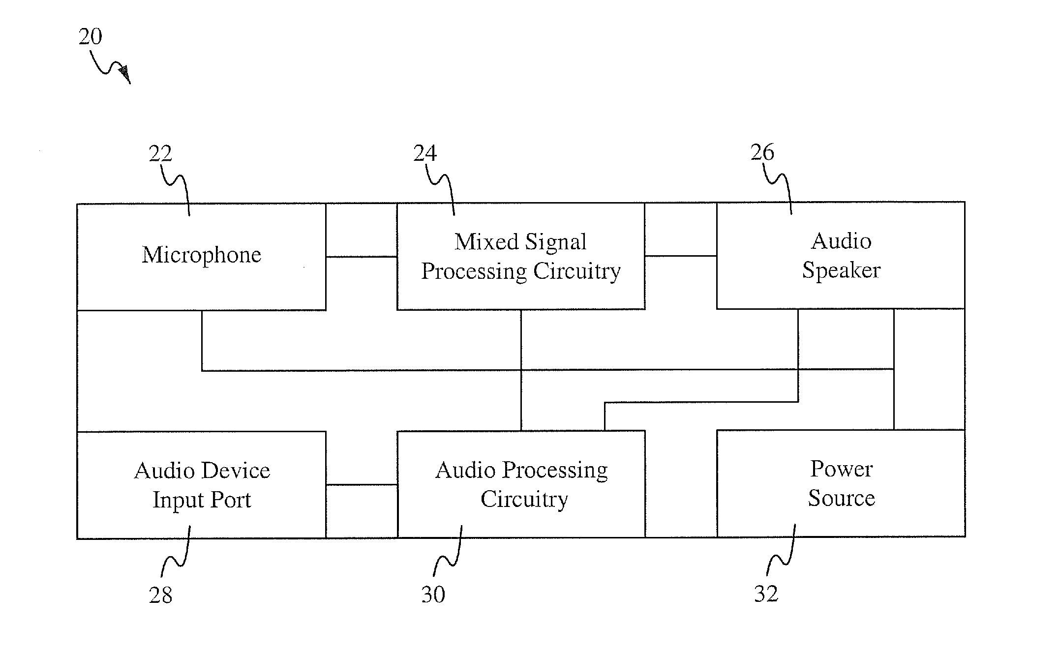
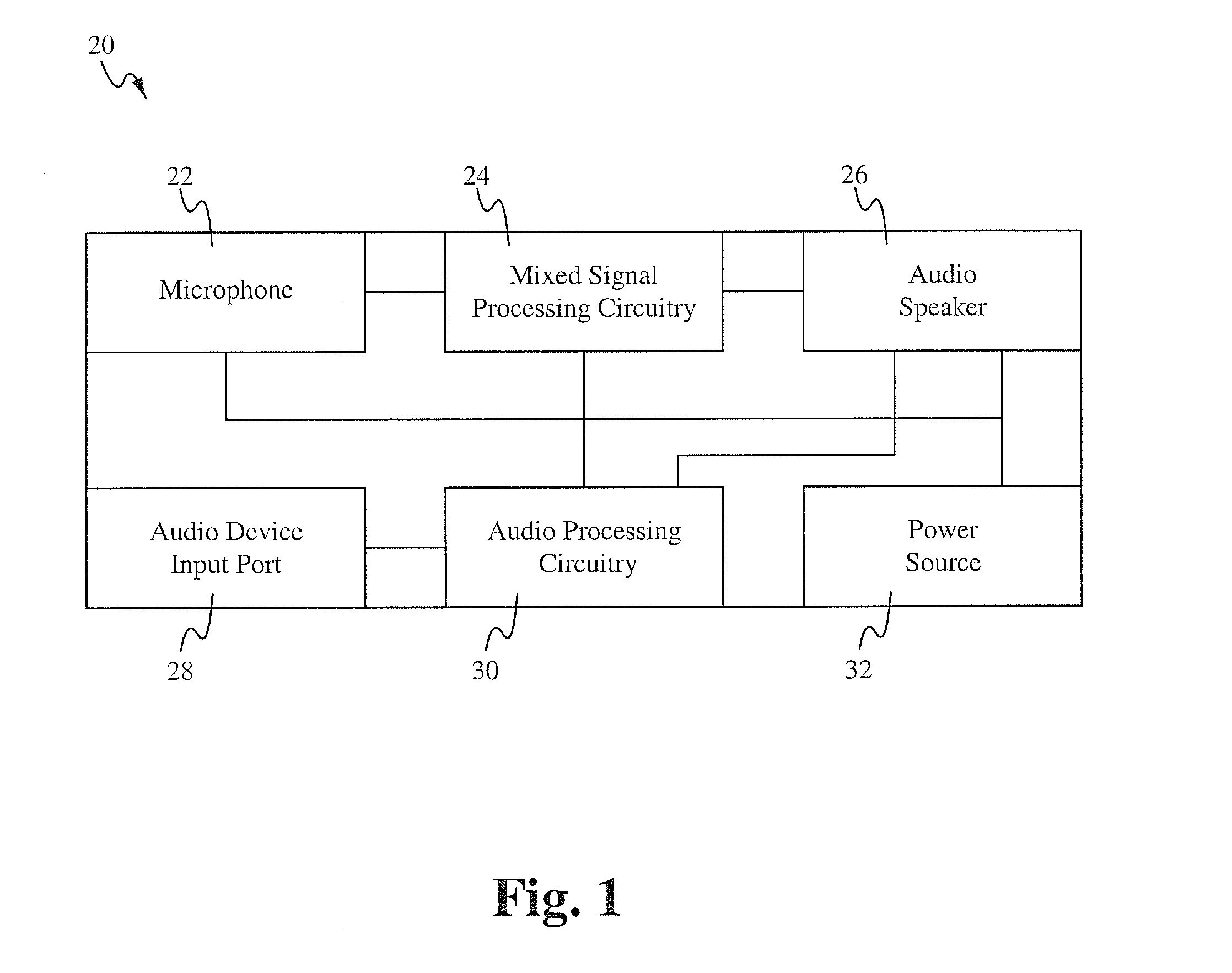
[0018]Embodiments of the present application are directed to a mixed signal processing circuit. Those of ordinary skill in the art will realize that the following detailed description of the mixed signal processing circuit is illustrative only and is not intended to be in any way limiting. Other embodiments of the mixed signal processing circuit will readily suggest themselves to such skilled persons having the benefit of this disclosure.

[0019]Reference will now be made in detail to implementations of the mixed signal processing circuit as illustrated in the accompanying drawings. The same reference indicators will be used throughout the drawings and the following detailed description to refer to the same or like parts. In the interest of clarity, not all of the routine features of the implementations described herein are shown and described. It will, of course, be appreciated that in the development of any such actual implementation, numerous implementation-specific decisions must ...


PUM


Abstract

A mixed signal processing circuit includes an analog to PWM converting circuit and a finite impulse response (FIR) filter having a multiple output tapped delay line and a summing and integration circuit. The mixed signal processing circuit converts an input analog signal to a PWM signal, forms a multi-level PWM signal from the PWM signal and one or more delayed versions of the PWM signal, and converts the multi-level PWM signal to an output analog signal. The analog to PWM converting circuit is implemented using a triangle waveform generator and a comparator. The FIR filter is implement using a resistive network to apply scaling coefficients of the FIR filter. The mixed signal processing circuit can be implemented within a noise cancellation headphone to generate a noise cancelling signal or generally in applications that would be benefitted from the combination of analog input/output and digital filter techniques.

Description

FIELD OF THE INVENTION[0001]The present invention relates to the field of mixed signal processing. More particularly, the present invention relates to the field of using multi-level pulse width modulated signal for real time noise cancellation.BACKGROUND OF THE INVENTION[0002]Signal processing is directed to performing operations on or analysis of signals. Signals are analog or digital electrical representations of time-varying or spatial-varying physical quantities. Digital signal processing and analog signal processing are sub-fields of signal processing. Digital signal processing is for signals that have been digitized. Analog signal processing is for signals that have not been digitized. More particularly, digital signal processing represents signals by a sequence of numbers or symbols and the processing of these signals. Analog signal processing is any signal processing conducted on analog signals by analog means. “Analog” indicates something that is mathematically represented ...

Claims


Application Information

Patent Timeline
IPC IPC(8): H03K7/08H04M1/00
CPCG10K11/1782G10K11/17855G10K11/17823G10K11/17873G10K11/17853G10K11/17885
Inventor CHEN, WALTER Y.
Owner MAXIM INTEGRATED PROD INC
Why Eureka
Try Eureka