Air battery module

a battery module and air technology, applied in the field of air battery modules, can solve the problems of gas retention in the battery, etc., and achieve the effects of reducing the volume of the power section in the housing, high output, and inhibiting the depletion of the electrolytic solution

Active Publication Date: 2012-05-10
TOYOTA JIDOSHA KK
View PDF3 Cites 11 Cited by
  • Summary
  • Abstract
  • Description
  • Claims
  • Application Information

AI Technical Summary

Benefits of technology

[0017]The present invention has a mode where a plurality of the power sections share an electrolytic solution in the housing, thereby the volume of the power section in the housing is lowered. In addition, since oxygen is dissolved in the electrolytic solution, by introducing the dissolved oxygen of the electrolytic solution into the cathode, it is possible to adequately carry out the cell reaction in the power section. Moreover, the invention can inhibit depletion of the electrolytic solution. Accordingly, the invention can provide an air battery module which is capable of attaining downsizing and obtaining high output.

Problems solved by technology

In the above embodiment employing an electrolytic solution in the electrolyte layer, problems such as depletion of the electrolytic solution and gas retention in the battery are caused due to, for example, volatilization of electrolytic solution as well as degradation of electrode material and electrolytic solution by the discharge.

Method used


Image

  • Air battery module
  • Air battery module
  • Air battery module

Examples


first embodiment

1. The First Embodiment

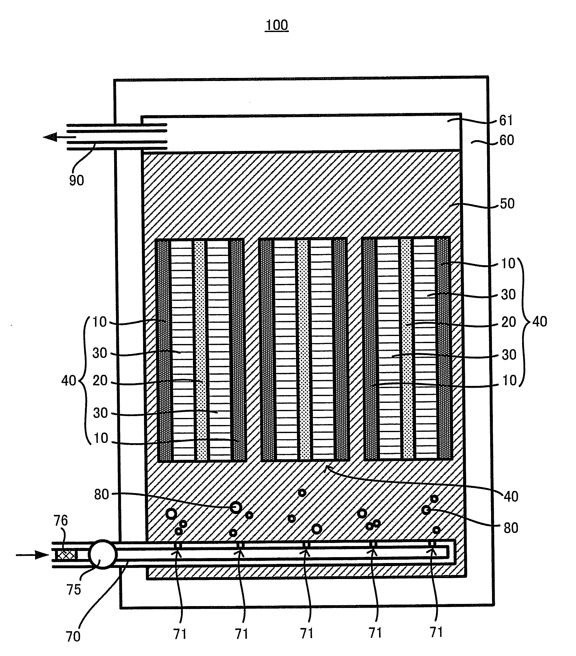
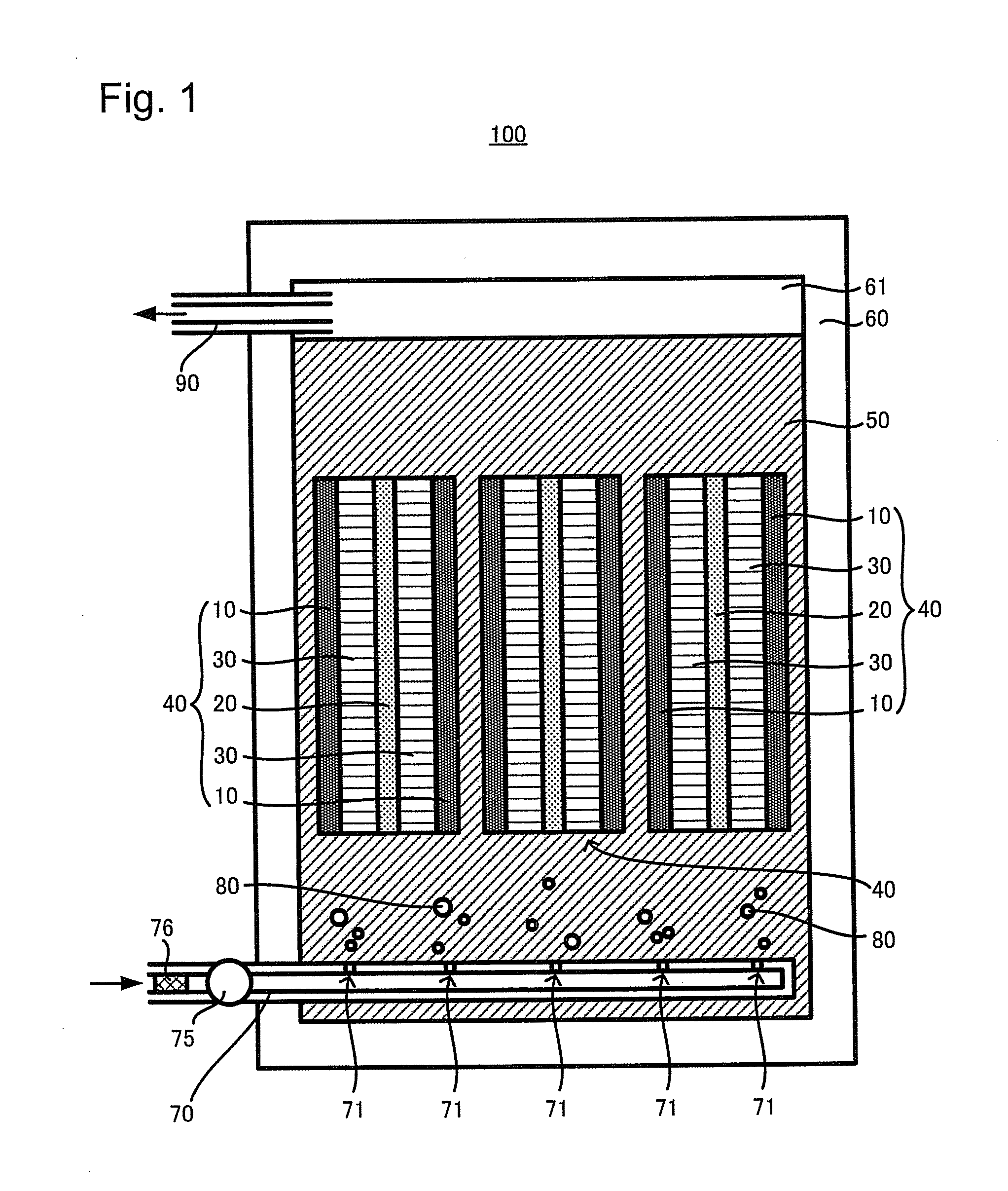
[0045]FIG. 1 is a plan schematically showing an air battery module 100 as the first embodiment of the invention. As shown in FIG. 1, the air battery module 100 comprises: a housing 60; and a plurality of power sections 40 being incorporated in the housing 60, each of which comprises: cathodes 10, 10; an anode 20; and electrolyte layers 30, 30 arranged between the cathodes 10, 10 and the anode 20. In the housing 60, an electrolytic solution 50 is reserved to immerse each of the plurality of power sections 40, 40, . . . ; one of the power sections 40 and another of the power sections 40 share the electrolytic solution 50. Further, a space 61 is provided at the upper part of the housing 60. On the other hand, a gas supply port 70 is inserted at the lower part of the housing 60. The gas supply port 70 comprises a pump 75 and a filter 76; through the pump 75 and the filter 76, gas can be supplied to inside of the housing. In the side surface at inside the housing o...

second embodiment

2. The Second Embodiment

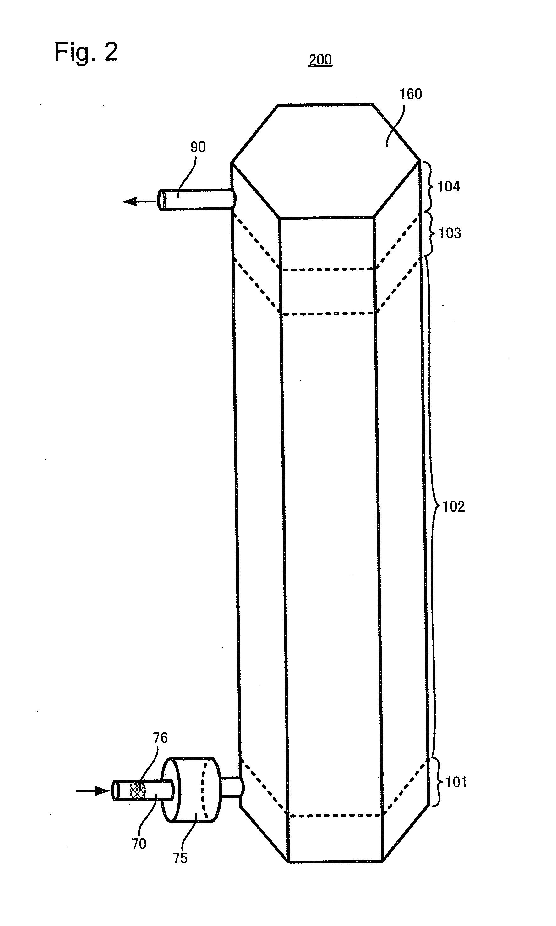
[0074]FIG. 2 is a plan schematically showing the appearance of the air battery module 200; and FIG. 3 is an exploded view schematically showing the internal structure of the air battery module 200. In FIGS. 2 and 3, to the elements having the same structure as those in the air battery module 100, the same reference numerals as those used in FIG. 1 are given and the explanation thereof is omitted. The air battery module 200 comprises: a substantially hexagonal column housing 160 of which cross-section is substantially regular hexagon; and battery components such as an electrolytic solution 50 and power sections 140, 140, . . . , wherein these battery components are incorporated in the housing 160. The air battery module 200 further comprises: a gas-supplying zone 101; a cell-stacking zone 102; a zone of excess electrolytic solution 103; and a gas-exhausting zone 104. Other than the limitation where the shape of the housing 160 is determined to be a container h...


PUM

PropertyMeasurementUnit
pressureaaaaaaaaaa
shapeaaaaaaaaaa
cylindrical shapeaaaaaaaaaa

Abstract

The present invention provides an air battery module comprising: a housing; a plurality of power sections incorporated in the housing; and an electrolytic solution which is filled in the housing to immerse the plurality of power sections and in which oxygen is dissolved, one of the power sections and another of the power sections sharing the electrolytic solution. The air battery module is capable of attaining downsizing and of obtaining high output.

Description

TECHNICAL FIELD[0001]The present invention relates to an air battery module.BACKGROUND ART[0002]An air battery is a battery employing oxygen as a cathode active material; at the time of discharge, air is introduced from outside the battery. So, compared with other type of batteries which incorporate active materials for both cathode and anode, it is possible to enlarge the occupancy rate of the anode active material in the battery case. Hence, in principle, the air battery has features that dischargeable electric power is large as well as downsizing and weight saving can be easily carried out. In addition, oxidation power of oxygen to be employed as the cathode active material is strong so that the electromotive force is relatively high. Moreover, since oxygen is a clean resource the amount of which is not limited, the air battery is environmentally-friendly. As above, air battery has many advantages; therefore it is expected to be used for batteries for mobile devices, electric veh...

Claims


Application Information

Patent Timeline
Patent Type & Authority Applications(United States)
IPC IPC(8): H01M8/22H01M4/86H01M8/04H01M2/02
CPCH01M12/06
Inventor NAKANISHI, SHINJI
Owner TOYOTA JIDOSHA KK
Why Eureka
Try Eureka