Endoscopic apparatus

Inactive Publication Date: 2012-05-10
FUJIFILM CORP
View PDF5 Cites 16 Cited by
  • Summary
  • Abstract
  • Description
  • Claims
  • Application Information

AI Technical Summary

Benefits of technology

[0010]An endoscopic apparatus emits illumination light with a desired light quality from a front end of an endoscope insertion portion. The endoscopic apparatus includes a semiconductor light source, an imaging unit and a light source control unit. The semiconductor light source generates the illumination light. The imaging unit adjusts an exposure time by using an electronic shutter. The light source control unit generates driving pulses to drive and light the semiconductor light source in accordance with an inputted target light quality. The light source control unit performs first pulse modulation control, second pulse modulation control and third pulse modulation control in descending order of the target light quantity. In the first pulse modulation control, the number of the driving pulses is reduced to shorten a lighting time of the semiconductor li

Problems solved by technology

By control of the light quantity only in this manner, there is a limit for securing a wide dynamic range or achieving a high light quantity resolution.
It is therefore difficult to control the quantity of light emission desirably with high accuracy.
Although a narrow pulse generator or a high-resolution type PWM controller may be used to cont

Method used


Image

  • Endoscopic apparatus
  • Endoscopic apparatus
  • Endoscopic apparatus

Examples


Embodiment Construction

[0020]An embodiment of the invention will be described below in detail with reference to the drawings.

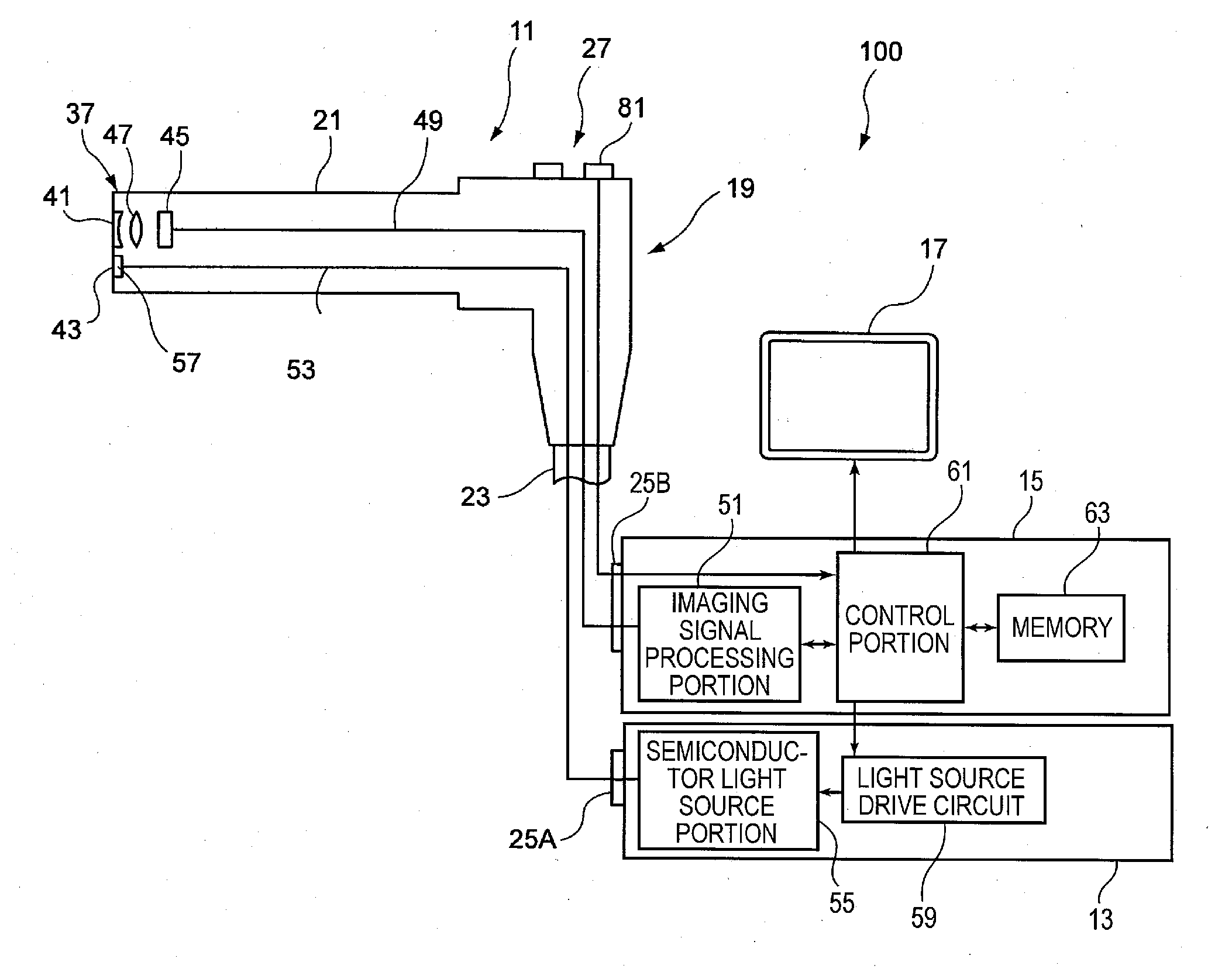
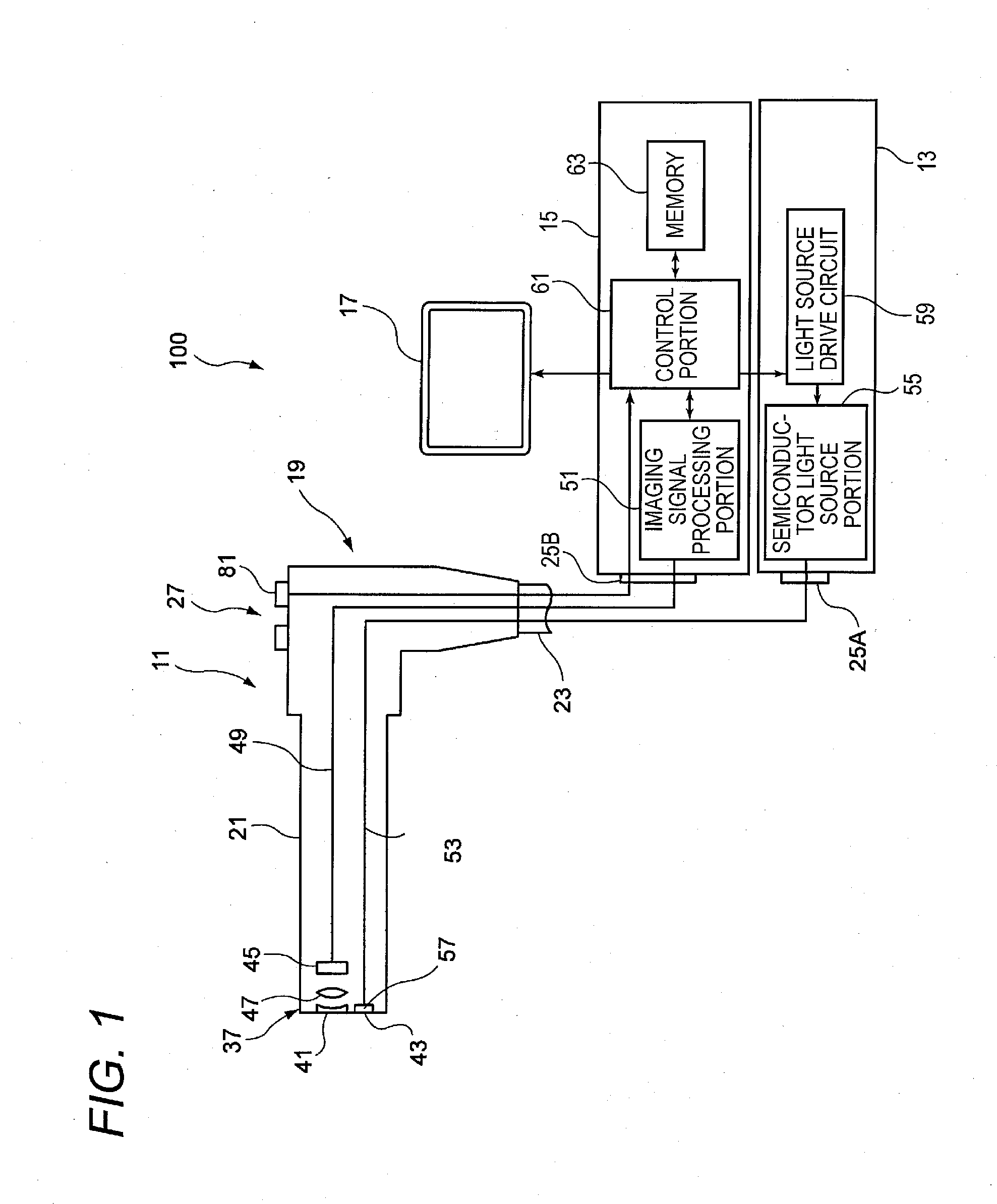
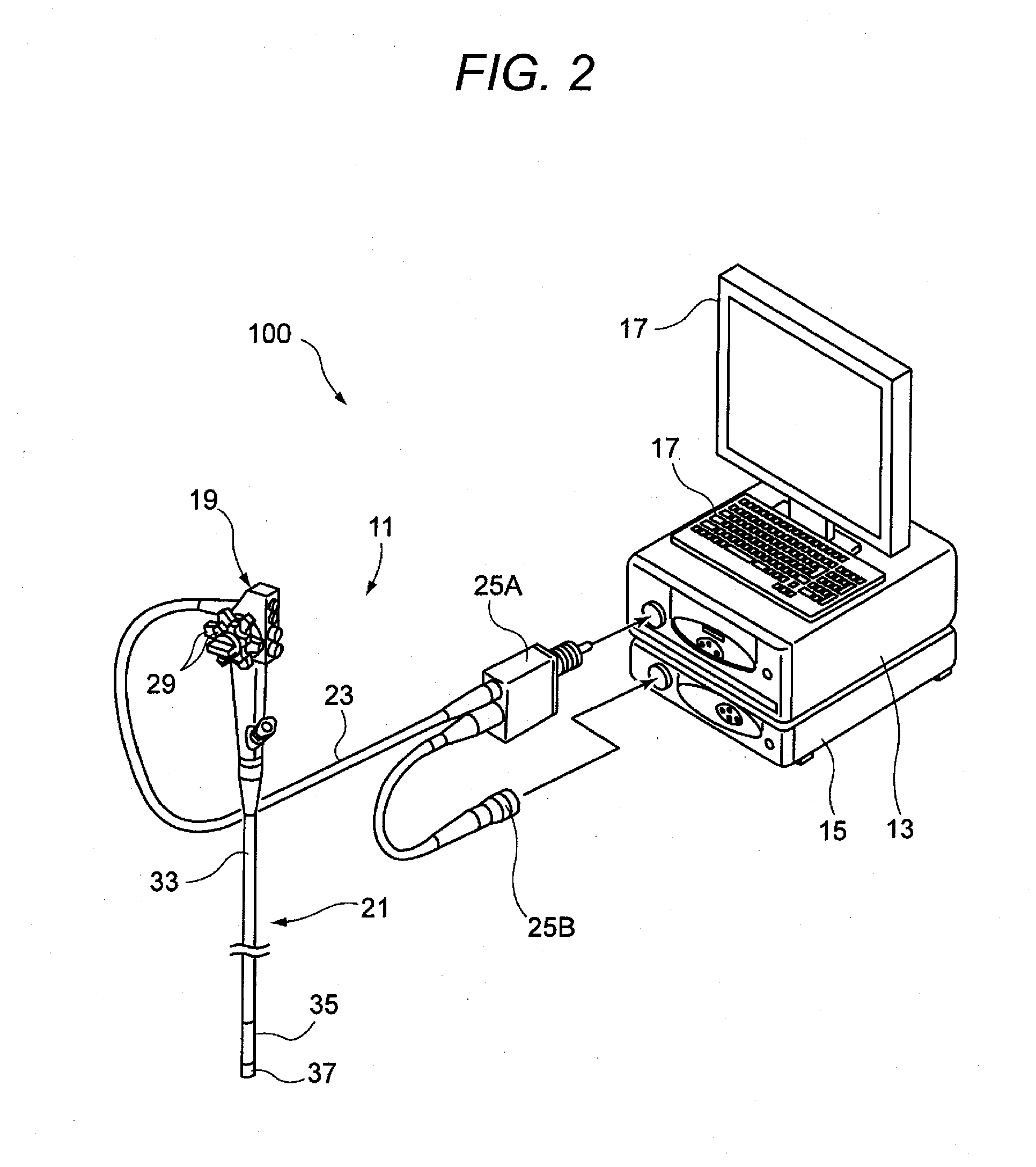
[0021]FIG. 1 is a view for explaining an embodiment of the invention, showing a configuration of an endoscopic apparatus having an endoscope and units the endoscope is connected to. FIG. 2 is an external view showing a specific example of the configuration of the endoscopic apparatus.

[0022]As shown in FIG. 1, an endoscopic apparatus 100 has an endoscope 11, a light source unit 13, a processor 15 for performing signal processing on a captured image, and a monitor 17. The endoscope 11 has a body operation portion 19 and an insertion portion 21 which is connected to the body operation portion 19 in order to be inserted into a subject (body cavity). A universal cable 23 is connected to the body operation portion 19. A front end of the universal cable 23 is connected to the light source unit 13 through a light guide (LG) connector 25A. In addition, an imaging signal is inputted to the pr...


PUM


Abstract

An endoscopic apparatus includes a semiconductor light source for generating illumination light and a light source control unit for generating driving pulses to drive and light the semiconductor light source. The light source control unit performs first, second and third pulse modulation controls in descending order of a target light quantity. In the first pulse modulation control, the number of the driving pulses is reduced so that a lighting time of the semiconductor light source is shortened to a predetermined lighting time for an exposure time of an electronic shutter within one frame. In the second pulse modulation control, the driving pulses are thinned at predetermined intervals so that pulse density is reduced in the lighting time. In the third pulse modulation control, pulse width of each of the driving pulses whose number is minimized in a region where the second pulse modulation control is performed is reduced.

Description

CROSS-REFERENCE TO RELATED APPLICATIONS[0001]This application claims the benefit of Japanese Patent Application No. 2010-251301, filed on Nov. 9, 2010, the entire contents of which are hereby incorporated by reference, the same as if set forth at length; the entire of which are incorporated herein by reference.BACKGROUND OF THE INVENTION[0002]1. Technical Field[0003]The present invention relates to an endoscopic apparatus.[0004]2. Description of Related Art[0005]Endoscopic apparatus for observing tissues in a body cavity has been known broadly. Generally, an endoscopic apparatus has a configuration in which white light emitted from a white light source such as a xenon lamp is supplied as illumination light to a to-be-observed region in a body cavity through a light guide and an image based on reflected light from the to-be-observed region irradiated with the white light is captured by an imaging device to generate an observation image. In recent years, an endoscopic apparatus having...

Claims


Application Information

Patent Timeline
IPC IPC(8): A61B1/04
CPCA61B1/00057A61B1/063A61B1/0653A61B1/0638A61B1/0655
Inventor SETO, YASUHIRO
Owner FUJIFILM CORP
Why Eureka
Try Eureka