Method and apparatus for wellbore perforation

a wellbore and perforation technology, applied in the direction of wellbore/well accessories, fluid removal, insulation, etc., can solve the problems of substantial reduction in production rate, serious safety and security concerns, and production rate reduction

Active Publication Date: 2012-05-17
HALLIBURTON ENERGY SERVICES INC +1
View PDF4 Cites 72 Cited by
  • Summary
  • Abstract
  • Description
  • Claims
  • Application Information

AI Technical Summary

Problems solved by technology

However, there are numerous problems with this approach.
First, the melt or debris from shaped charges usually reduces the permeability of the producing formations resulting in a substantial reduction in production rate.
Second, these techniques involve the transportation and handling of high power explosives and are causes of serious safety and security concerns.
Third, the energy jet into the formation also produces fine grains that can plug the pore throat, thereby reducing the production rate.
Highly viscous fluids do not flow easily.
In extreme cases, these factors reduce the flow rate to zero, halting production entirely.
Newer technologies have employed lasers to make perforations, but perforation depths have been limited to about 4 inches after which further penetration is hampered by hole taper issues and the lack of efficient debris removal.
However, there are no teachings regarding the effect of drilling fluid or other media in the wellbore on the transmission of the laser energy to the wellbore wall, nor are there any teachings regarding handling of any debris generated by the laser operation.

Method used


Image

  • Method and apparatus for wellbore perforation
  • Method and apparatus for wellbore perforation
  • Method and apparatus for wellbore perforation

Examples


example

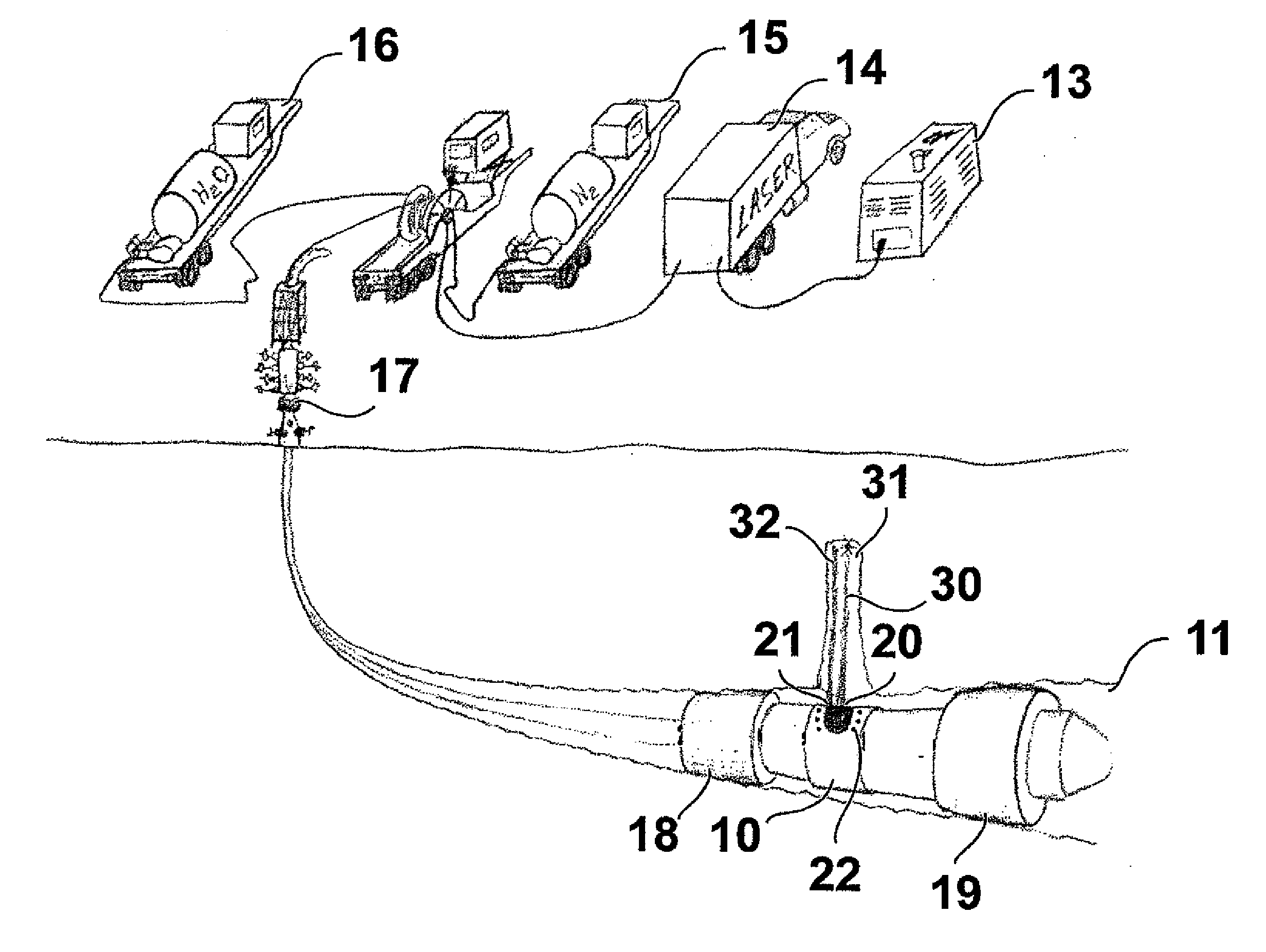
[0024]In this example, a 1750 psi water jet was determined to be sufficient to remove thermally spalled debris and melt from a sandstone target without removing the underlying virgin material not previously subjected to significant optical power levels. A persepex water containment vessel was positioned above a secondary water containment vessel on the top of an optical bench. A Berea sandstone target was placed on a lab jack within the water containment vessel. The target was aligned to the laser input to the chamber by use of a visible guide beam delivered by an optical head comprising a QBH-fiber terminal, collating optics, focusing lens and protective window. A 300 mm focusing lens was installed such that a diverging beam could be projected with adequate spot size onto the target face to attain desired beam irradiance with 4 kW total laser power, and to provide adequate standoff from the target to avoid splash back of debris. A ball valve was inserted after the pressure washer s...


PUM


Abstract

A method for wellbore perforation in which a section of the wellbore to be perforated is isolated and purged of wellbore fluid to provide a clear path for laser beam transmittal. A laser beam emitter in the purged wellbore section transmits a laser beam pulse from the laser beam emitter to a target area of a sidewall and formation lithology of the purged wellbore section, thereby altering a mechanical property of a material of the sidewall and formation lithology and producing material debris. A liquid jet pulse of a liquid is transmitted immediately following termination of the laser beam pulse to the target area, thereby removing the material debris from the target area. This cycle is then repeated until the desired perforation depth has been achieved.

Description

BACKGROUND OF THE INVENTION[0001]1. Field of the Invention[0002]This invention relates to a method and apparatus for perforating a wellbore. In one aspect, this invention relates to the use of laser energy for perforating wellbores. In one aspect, this invention relates to a method and apparatus for removal of solids generated during the wellbore perforation process. In one aspect, this invention relates to a method of providing a clear path for transmission of laser energy in a wellbore.[0003]2. Description of Related Art[0004]Once the drilling of a well has been completed, fluid flow into the well is initiated by perforation of the well casing or liner. Such perforations are created using shaped charges for establishing flow of oil or gas from the geologic formations into the wellbore. The perforations typically extend a few inches into the formation. However, there are numerous problems with this approach. First, the melt or debris from shaped charges usually reduces the permeabi...

Claims


Application Information

Patent Timeline
Patent Type & Authority Applications(United States)
IPC IPC(8): E21B43/11
CPCE21B36/04E21B7/14E21B43/11
Inventor KLEEFISCH, MARKHAWTHORN, COLINREYNOLDS, HENRY DAVIDSKINNER, NEAL GREGORYSURJAATMADJA, JIM BASUKISCHULTZ, ROGER LYNNHUNTER, TIMOTHY HOLIMAN
Owner HALLIBURTON ENERGY SERVICES INC
Why Eureka
Try Eureka