Lock device and electric power steering system

Inactive Publication Date: 2012-05-17
JTEKT CORP
View PDF3 Cites 5 Cited by
  • Summary
  • Abstract
  • Description
  • Claims
  • Application Information

AI Technical Summary

Benefits of technology

[0015]It is an object of the invention to provide a lock device that is able to reliably maintain the locked state with low power consumption while operating a lock cancellation maintaining member using an electric drive unit without being affected by an electrical trouble.

Problems solved by technology

Therefore, if the key portion is provided at an instrument panel at a driver's seat, the lock mechanism portion is located in front of the knee of a driver, which may impose restrictions on the strength and installation position of the lock mechanism portion.
However, in the structure in which the locking cancellation maintaining member is operated by electric drive unit such as a solenoid, malfunction due to an electrical problem (e.g., breakage of a harness, disconnection of a connector, or an instantaneous reduction in battery voltage) may occur.

Method used


Image

  • Lock device and electric power steering system
  • Lock device and electric power steering system
  • Lock device and electric power steering system

Examples


Embodiment Construction

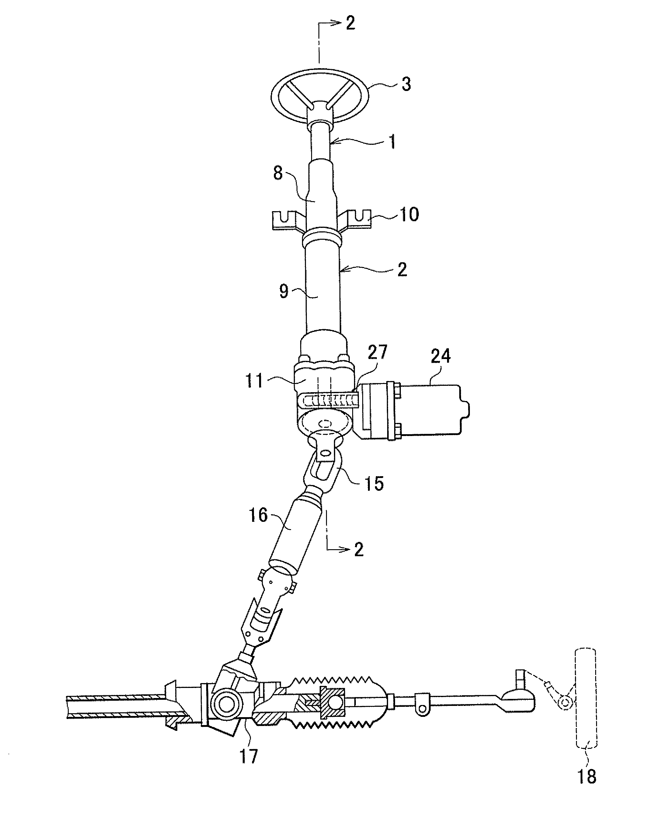
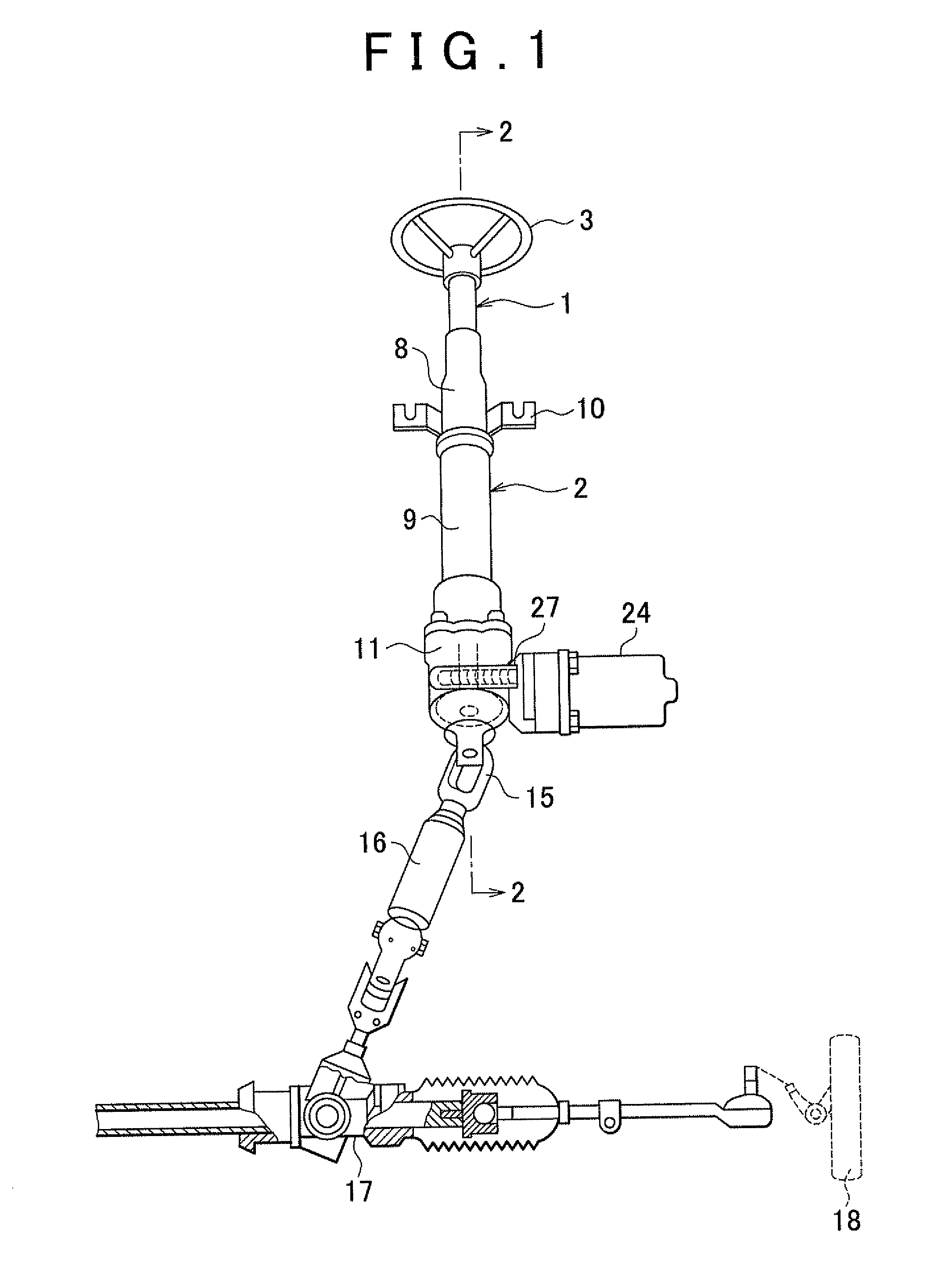
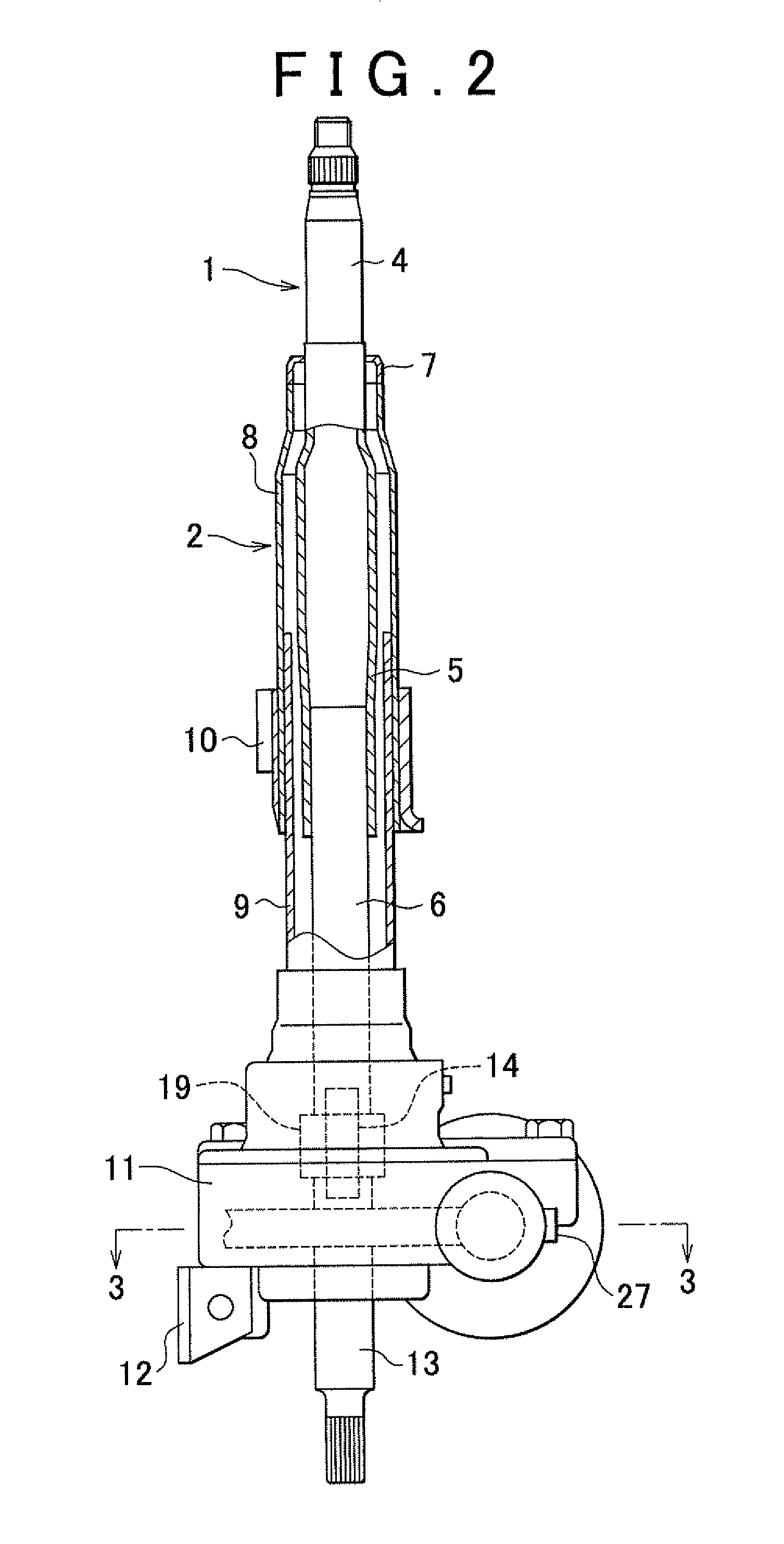
[0035]Hereafter, an embodiment of the invention will be described with reference to the accompanying drawings. As shown in FIG. 1 and FIG. 2, an input shaft 1 of an electric power steering system is rotatably supported by a steering column 2. The input shaft 1 includes an upper shaft 4 and a lower shaft 6. A steering wheel 3 is attached to the upper shaft 4. The lower shaft 6 is fitted in a tubular portion 5 formed at a lower end portion of the upper shaft 4 such that relative rotation between the lower shaft 6 and the tubular portion 5 is restricted and such that relative displacement between the tubular portion 5 and the lower shaft 6 in the axial direction is allowed if an axial force equal to or larger than a predetermined value is applied. Accordingly, if a driver hits the steering wheel 3 upon a vehicle collision and an axial force equal to or larger than the predetermined value is applied to the input shaft 1, the upper shaft 4 is displaced relative to the lower shaft 6 in th...


PUM


Abstract

A lock device that restricts movement of a movable body includes: a lock member that is engageable with an engagement portion formed at the movable body; an urging member that urges the lock member in a direction away from the engagement portion; and an actuator that moves the lock member toward the engagement portion to engage the lock member with the engagement portion against an urging force generated by the urging member.

Description

INCORPORATION BY REFERENCE[0001]The disclosure of Japanese Patent Applications No. 2010-255737 filed on Nov. 16, 2010 and No. 2011-097123 filed on Apr. 25, 2011 including the specification, drawings and abstract is incorporated herein by reference in its entirety.BACKGROUND OF THE INVENTION[0002]1. Field of the Invention[0003]The invention relates to a lock device and an electric power steering system.[0004]2. Description of Related Art[0005]Conventional lock devices are described in, for example, Japanese Patent Application Publication No. 2010-219816 (JP 2010-219816 A) and Japanese Patent Application Publication No. 2002-308049 (JP 2002-308049).[0006]JP 2001-219816 describes a column-type electric power steering system provided with a steering lock device. An engagement portion is formed at a worm shaft side (input side), the worm shaft transmitting the rotation of an electric motor to a speed reducer, or at an electric motor output shaft side. A locked state is achieved by insert...

Claims


Application Information

Patent Timeline
IPC IPC(8): B62D5/04B62D1/16B60R25/0215
CPCB60R25/02153H01F7/1615B62D5/0409B62D5/04Y10T70/5956
Inventor MORI, YUTAKASHIBATA, YOSHIYUKI
Owner JTEKT CORP
Why Eureka
Try Eureka