Voltage conversion apparatus and electrical load driving apparatus

a technology of voltage conversion apparatus and driving apparatus, which is applied in the direction of power conversion system, dc-dc conversion, instruments, etc., can solve problems such as noise generation, and achieve the effect of effectively reducing noise and radiating heat of switching elements

a technology of voltage conversion apparatus and driving apparatus, which is applied in the direction of power conversion system, dc-dc conversion, instruments, etc., can solve problems such as noise generation, and achieve the effect of effectively reducing noise and radiating heat of switching elements

US20120119723A1Active Publication Date: 2012-05-17TOYOTA JIDOSHA KK +1

Image

  • Voltage conversion apparatus and electrical load driving apparatus
  • Voltage conversion apparatus and electrical load driving apparatus
  • Voltage conversion apparatus and electrical load driving apparatus

Examples


Embodiment Construction

[0041]In the following, the best mode for carrying out the present invention will be described in detail by referring to the accompanying drawings.

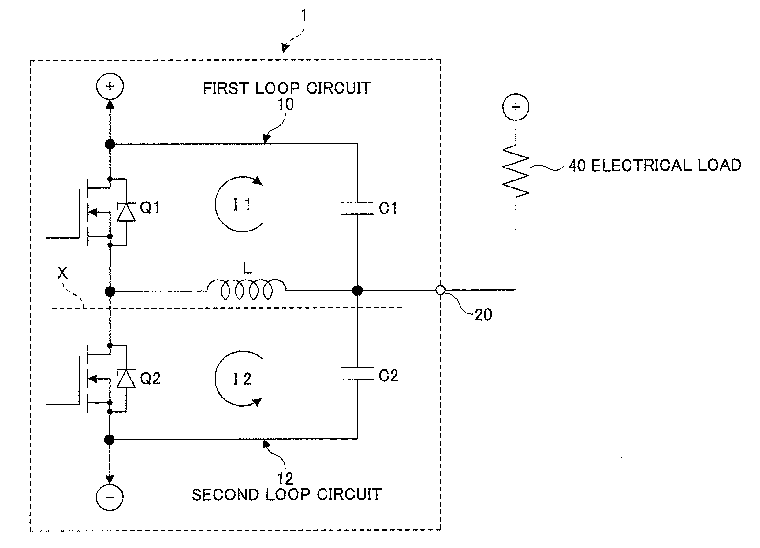
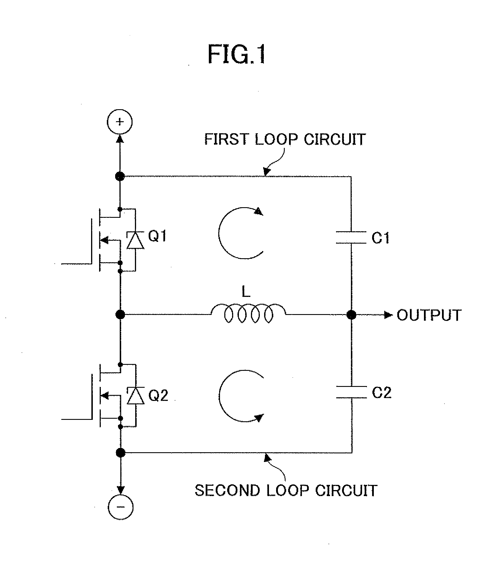
[0042]FIG. 3 is a diagram for illustrating a circuit configuration of a voltage conversion apparatus 1 according to one embodiment of the present invention. The circuit configuration of the voltage conversion apparatus. 1 according to the embodiment itself is equivalent to the circuit configuration of the conventional DC-DC converter shown in FIG. 1.

[0043]Specifically, the voltage conversion apparatus 1 is a non-isolated DC-DC converter employing synchronous rectification. The voltage conversion apparatus 1 has first and second loop circuits 10 and 12. An output terminal 20 of the voltage conversion apparatus 1 is connected to an electrical load 40 to be driven. The first and second loop circuits 10 and 12 share an inductance L.

[0044]The first loop circuit 10 has a switching element Q1 and a capacitor C1 in addition to the inductance L. T...


PUM


Abstract

A voltage conversion apparatus is disclosed in which a current passes through first and second loop circuits alternately in accordance with ON / OFF operation of a first switching element provided in the first circuit. The direction of a magnetic field through the first loop circuit formed at the ON operation is the same as a direction of a magnetic field through the second loop circuit formed at the OFF operation. The first loop circuit and the second loop circuit are provided on opposite sides of a printed circuit board, respectively, in such a manner that the first loop circuit and the second loop circuit are opposed to each other. A heat sink is provided on a surface of the printed circuit board. A solid pattern of a metal material is provided on an inner layer of the printed circuit board to be connected to the heat sink via a through hole.

Description

TECHNICAL FIELD[0001]The present invention is related to a voltage conversion apparatus having a first loop circuit and a second loop circuit which share an inductance component and is also related to an electrical load driving apparatus which uses the voltage conversion apparatus.BACKGROUND ART[0002]JP2005-110452 discloses a switching power supply circuit having a primary circuit connected to a primary coil of a transformer and a secondary circuit connected to a secondary coil of a transformer, wherein an electrode pattern for the primary circuit and an electrode pattern for the secondary circuit are disposed such a manner that they are opposed to each other. An insulating layer between the electrode patterns functions as a dielectric for a capacitor and thus forms an equivalent capacitor. The equivalent capacitor functions as a capacitor for noise reduction.[0003]A non-isolated DC-DC converter, for example, as shown in FIG. 1, is provided with a first loop circuit and a second loo...

Claims


Application Information

Patent Timeline
17 May 2012
Publication
US20120119723A1
IPC
G05F3/08
CPC
H02M3/158; H02M3/00; H02M3/003
Inventors
MIZUTANI, KOICHI; NAITO, TAKAYUKI