Directional coupler
a directional coupler and directional technology, applied in the direction of coupling devices, electrical devices, waveguides, etc., can solve the problems of deterioration of directionality and inability to obtain high coupling degree, and achieve favorable directivity and high coupling degree
- Summary
- Abstract
- Description
- Claims
- Application Information
AI Technical Summary
Benefits of technology
Problems solved by technology
Method used
Image

Examples
first embodiment
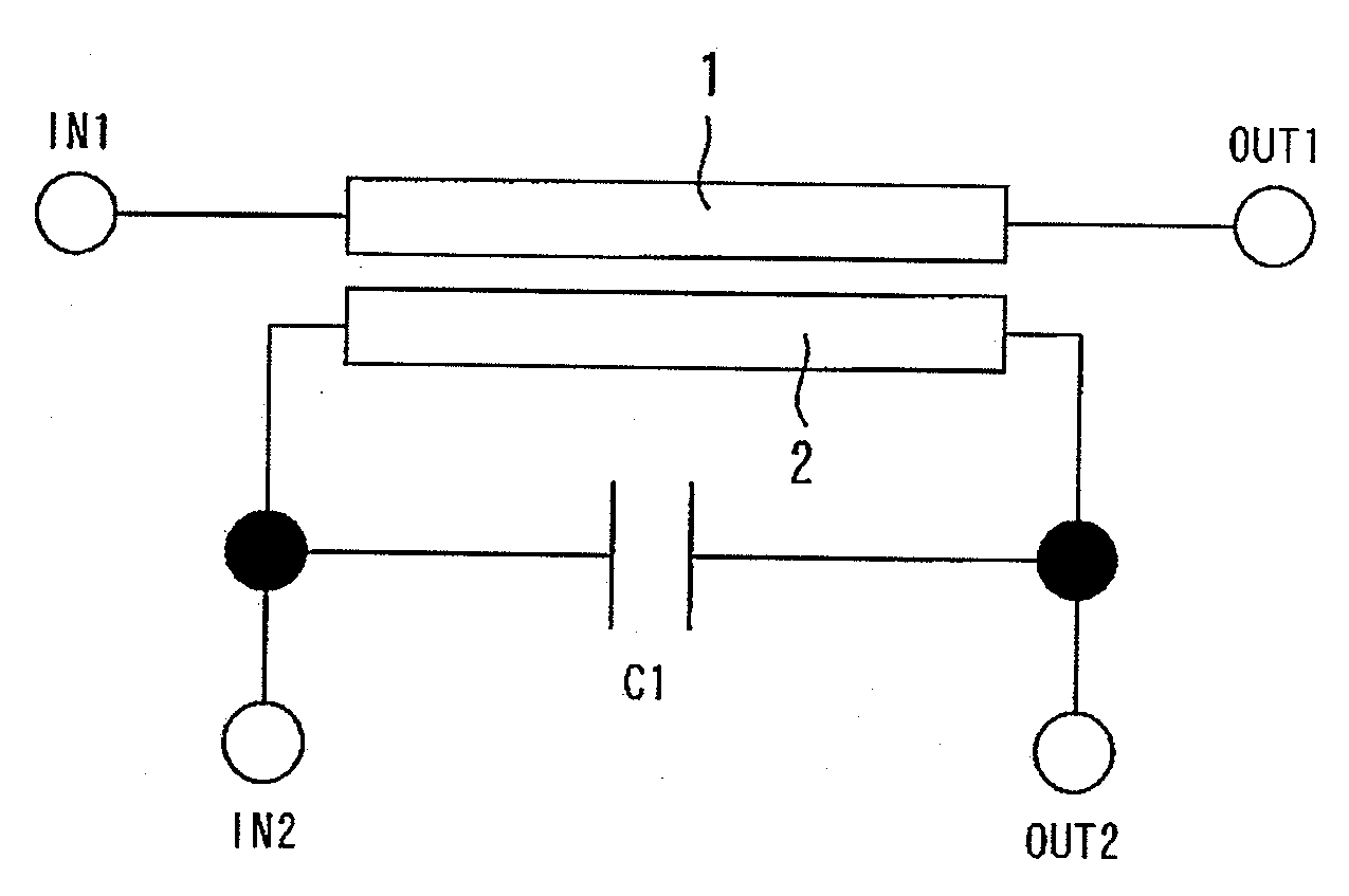
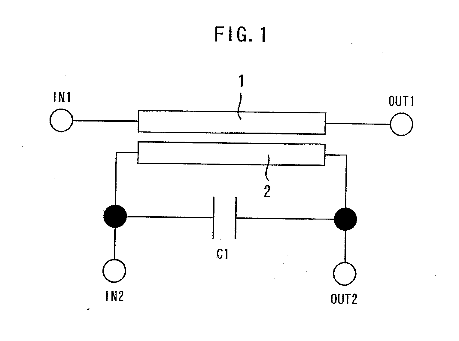
[0038]FIG. 1 is a diagram showing a directional coupler according to the first embodiment of the present invention. A main strip line 1 is connected between an input terminal IN1 and an output terminal OUT1. The main strip line 1 transmits high-frequency signals. A sub strip line 2 is connected between an input terminal IN2 and an output terminal OUT2. The sub strip line 2 is located in parallel to the main strip line 1, and is electromagnetically connected to the main strip line 1.
[0039]In the present embodiment, a capacitor C1 is connected in parallel to the sub strip line 2. An LC resonant circuit is constituted by the inductance L of the main strip line 1 and the sub strip line 2 and the capacitance C of the capacitor C1. This LC resonant circuit resonates with respect to the propagating high-frequency signals from the input terminal IN1 to the output terminal OUT2. When the frequency of the propagating high-frequency signals from the input terminal IN1 to the output terminal OU...
second embodiment
[0048]FIG. 8 is a diagram showing a directional coupler according to the second embodiment of the present invention. The resistance R1 connected to the capacitor C1 in series is added to the constitution of the modified example 1 of the first embodiment. Thereby, the Q value can be decreased to blunt the peak of the LC resonance of the directional coupler and the capacitor C1. Therefore, the frequency range of the improved directivity, can be widened in comparison with the first embodiment.
[0049]FIG. 9 is a diagram showing a modified example of the directional coupler according to the second embodiment of the present invention. The resistance R1 connected to the capacitor C1 in series is added to the constitution of the modified example 1 of the first embodiment. Thereby, the identical effect as the effect of the second embodiment can be obtained.
third embodiment
[0050]FIG. 10 is a diagram showing a directional coupler according to the third embodiment of the present invention. The inductor L1 connected to the capacitor C1 in series is added to the constitution of the first embodiment is added. Thereby, the Q value can be enlarged, and the peak of the LC resonance of the directional coupler and the capacitor C1 can be sharpened. Therefore, the absolute value of the directivity to be improved in a narrow frequency range can be enlarged in comparison with the first embodiment. Furthermore, the capacitance of the capacitor C1 can be reduced in comparison with the first embodiment.
[0051]FIG. 11 is a diagram showing a modified example of the directional coupler according to the third embodiment of the present invention. The inductor L1 connected to the capacitor C1 in series is added to the constitution of the first modified example of the first embodiment is added. Thereby, the identical effect as the effect of the third embodiment can be obtain...
PUM
 Abstract
Description
Claims
Application Information
 - R&D Engineer
- R&D Manager
- IP Professional
- Industry Leading Data Capabilities
- Powerful AI technology
- Patent DNA Extraction
Browse by: Latest US Patents, China's latest patents, Technical Efficacy Thesaurus, Application Domain, Technology Topic.
© 2024 PatSnap. All rights reserved.Legal|Privacy policy|Modern Slavery Act Transparency Statement|Sitemap