Multilayer band-pass filter

Active Publication Date: 2012-05-17
MURATA MFG CO LTD
View PDF3 Cites 16 Cited by
  • Summary
  • Abstract
  • Description
  • Claims
  • Application Information

AI Technical Summary

Benefits of technology

[0021]With this configuration, because the inductor electrodes have substantially the same distance to the ground electrode being substantially parallel with the mounting surface, the impedance of each inductor can be easily designed, and stable characteristics are obtainable.
[0022]With preferred embodiments of the present invention, because there is no need to widen each of the jump-coupli

Problems solved by technology

Therefore, there is a problem in that Q of the filter decreases and attenuation characteristics deteriorate.
However, the displacement of a capacitor electrode of a resonator in the la

Method used


Image

  • Multilayer band-pass filter
  • Multilayer band-pass filter
  • Multilayer band-pass filter

Examples


first preferred embodiment

[0036]A multilayer band-pass filter according to a first preferred embodiment is described with reference to FIGS. 2 to 5B.

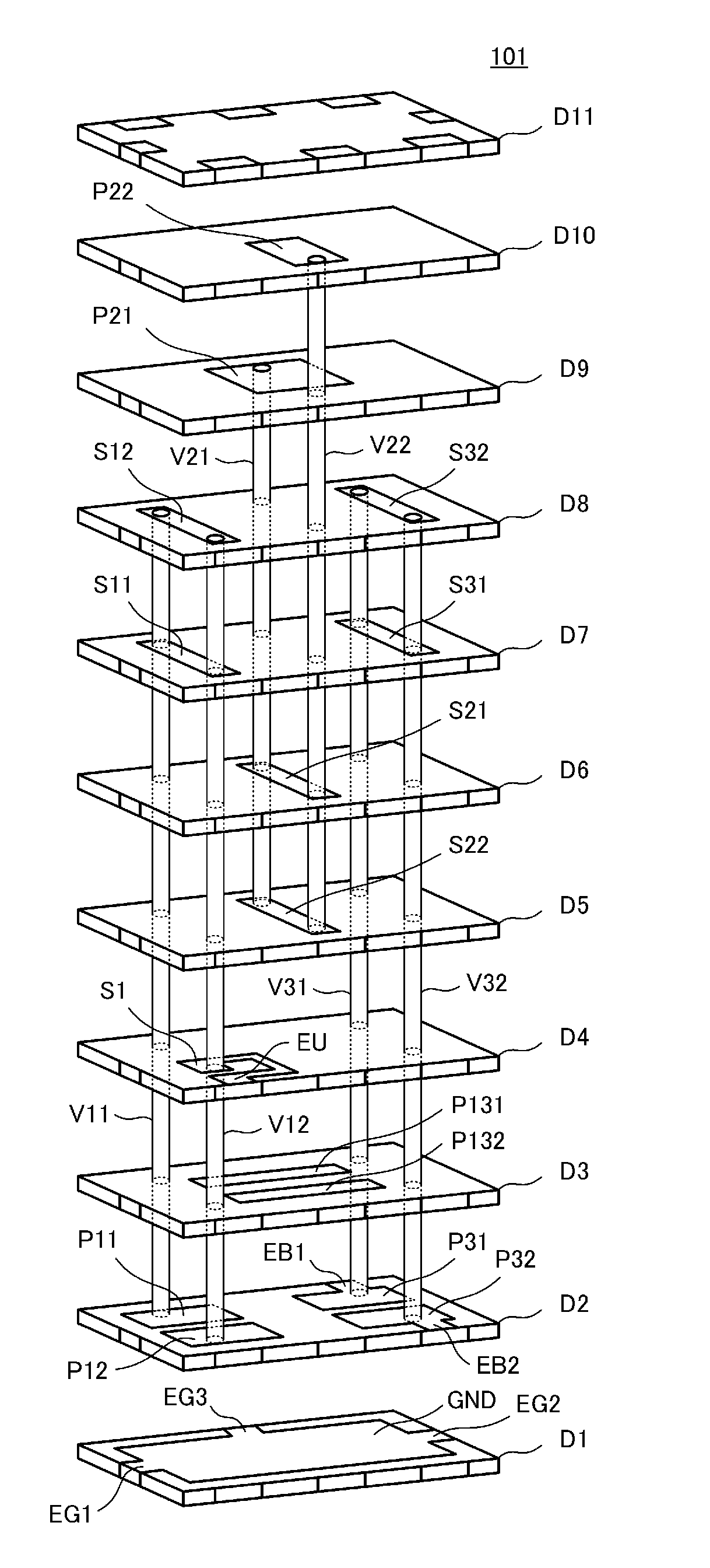
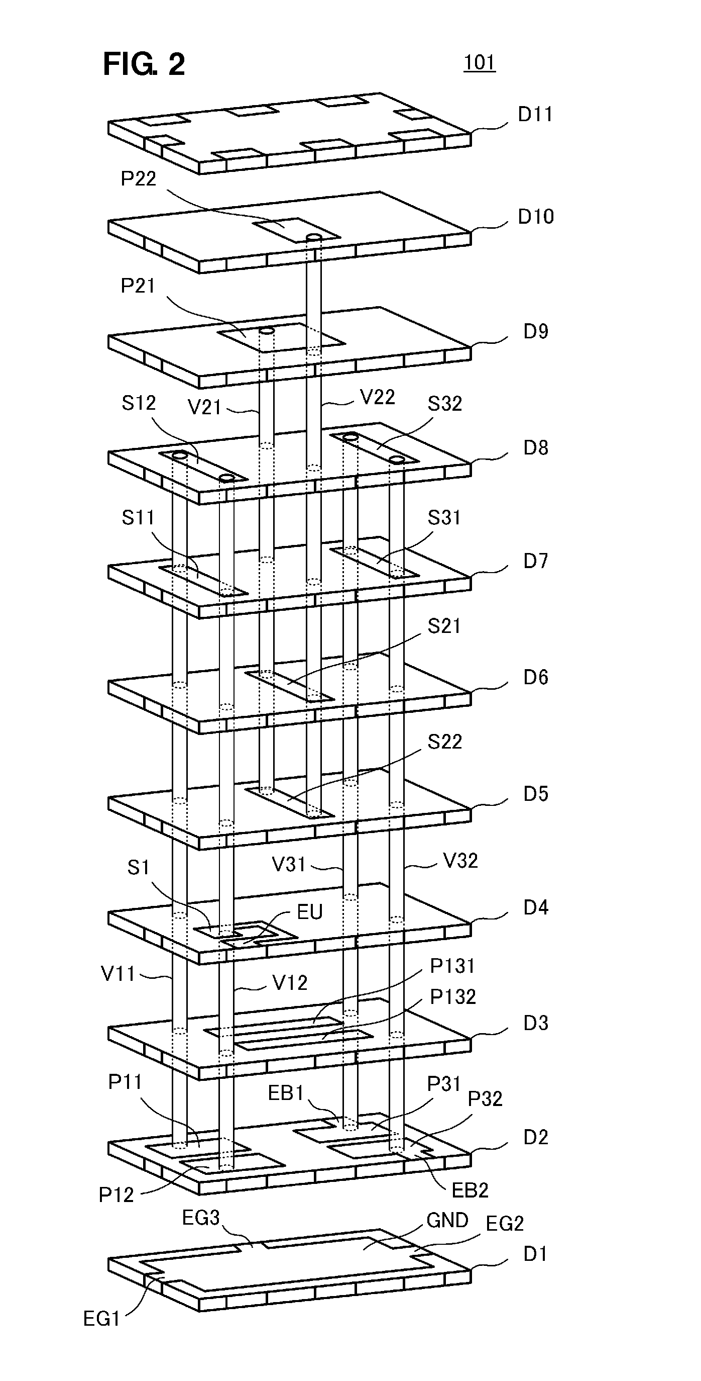
[0037]FIG. 2 is an exploded perspective view of a multilayer band-pass filter 101 according to the first preferred embodiment.

[0038]FIG. 3 is an external perspective view of the multilayer band-pass filter 101. FIG. 4 is an equivalent circuit diagram of the multilayer band-pass filter 101.

[0039]First, a configuration of the multilayer band-pass filter 101 according to the first preferred embodiment based on its equivalent circuit is described with reference to FIG. 4. The multilayer band-pass filter 101 preferably is a band-pass filter that includes an unbalanced terminal UB and balanced terminals B1 and B2 and has the balanced-unbalanced transforming function. For the present preferred embodiment, the LC parallel resonator connected to the unbalanced terminal UB is defined as a first-stage LC parallel resonator, the LC parallel resonator connected to the balanc...

second preferred embodiment

[0065]FIG. 6 is an exploded perspective view of a multilayer band-pass filter 102 according to a second preferred embodiment of the present invention. FIG. 7 is an equivalent circuit diagram of the multilayer band-pass filter 102. The multilayer band-pass filter 101 according to the first preferred embodiment of the present invention includes three LC parallel resonators, whereas the multilayer band-pass filter 102 according to the second preferred embodiment of the present invention includes four LC parallel resonators.

[0066]Referring to FIG. 6, the line electrodes S32 and S31 of the third-stage LC parallel resonator are disposed on the upper surfaces of the dielectric layers D5 and D6, respectively. For the present preferred embodiment, of the four LC parallel resonators, the LC parallel resonator connected to an unbalanced terminal is defined as a first-stage LC parallel resonator, and the LC parallel resonator connected to the balanced terminals is defined as a fourth-stage LC p...

third preferred embodiment

[0076]FIG. 8 is an exploded perspective view of a multilayer band-pass filter 103 according to a third preferred embodiment of the present invention. The multilayer band-pass filter 103 is different from the multilayer band-pass filter according to the first preferred embodiment of the present invention in that it includes a matching circuit at the balanced side.

[0077]Inductor electrodes S33 and S34 to perform matching at the balanced side are disposed on the upper surface of a dielectric layer D12. First ends of the inductor electrodes S33 and S34 to perform matching at the balanced side are electrically connected to the lead electrodes EB1 and EB2, respectively, and second ends thereof are electrically connected to the via electrodes V31 and V32, respectively.

[0078]A capacitor electrode P33 is disposed on the upper surface of the dielectric layer D3. The capacitor electrode P33 is opposed to the inductor electrodes S33 and S34 to perform matching at the balanced side and is arrang...


PUM


Abstract

In a multilayer band-pass filter, each of first-stage to third-stage LC parallel resonators includes capacitor electrodes, via electrodes, and a line electrode. Jump-coupling capacitor electrodes face the capacitor electrodes of the first-stage and third-stage LC parallel resonators. The direction in which the inductor electrode extends from the capacitor electrodes of each of the first-stage and third-stage LC parallel resonators is opposite to the direction in which the inductor electrode extends from the capacitor electrodes of the second-stage LC parallel resonator.

Description

BACKGROUND OF THE INVENTION[0001]1. Field of the Invention[0002]The present invention relates to a multilayer filter that includes a plurality of LC parallel resonators including inductors having a loop shape and capacitor electrodes.[0003]2. Description of the Related Art[0004]A typical radio-frequency band-pass filter suited for miniaturization and low cost of manufacturing is configured such that a plurality of LC resonators is disposed in a laminate of dielectric layers and electrode layers.[0005]Examples of such a multilayer band-pass filter are disclosed in Japanese Unexamined Patent Application Publication No. 2006-67221 and International Publication No. WO 2007-119356.[0006]Japanese Unexamined Patent Application Publication No. 2006-67221 discloses a three-stage multilayer filter in which the first-stage and third-stage resonators are jump-coupled by a coupling capacitor C3, as illustrated in FIG. 1 thereof. The jump-coupling capacitor C3 is configured such that an electrode...

Claims


Application Information

Patent Timeline
IPC IPC(8): H01P1/203
CPCH01P1/20345H03H7/09H03H7/1708H03H2001/0085H03H7/1775H03H7/42H03H7/1766
Inventor SASAKI, HIROYUKIMASUDA, HIROSHITANIGUCHI, TETSUO
Owner MURATA MFG CO LTD
Why Eureka
Try Eureka