Magnetic element

a technology of magnetic elements and lead wires, applied in the field of magnetic elements, can solve the problems of wires being prone to breakage, thin wires being further liable to breakage, etc., and achieve the effect of reducing the contact position of the end, preventing breakage of lead wires more effectively, and increasing the number of windings of the coil

Active Publication Date: 2012-05-17
SUMIDA CORP
View PDF9 Cites 8 Cited by
  • Summary
  • Abstract
  • Description
  • Claims
  • Application Information

AI Technical Summary

Benefits of technology

[0012]In such a structure, the end of the lead wire forming the coil is guided to the binding terminal part while the end is prevented from contacting the outer peripheral edge of the one flange part of the first core member. Accordingly, it is possible to further decrease the contact position of the end, and the lead wire can be prevented from breaking at the contact portion of the aforementioned outer peripheral edge and the end even when the magnetic element is used in an environment where vibrations are given. Since breakage of the lead wire can thereby be prevented more effectively in an environment where vibrations are given, the number of windings of the coil can be increased using a thin wire having a smaller diameter as the lead wire, and it is possible to increase the inductance value of the magnetic element.
[0013]Moreover, in another aspect of the magnetic element of the present invention, in addition to the above-described invention, preferably, the terminal member is provided with a vertical extending portion and a horizontal extending portion continuing to the vertical extending portion, the vertical extending portion extends along outer wall faces of a second corner part out of the plural corner parts of the base member and the second core member

Problems solved by technology

However, when the end of the lead wire contacts edges of such a core and a spacer, the lead wire may break especially when the magnetic element is used in an environment where vibrations are given.
In particular, when the number of

Method used


Image

  • Magnetic element
  • Magnetic element
  • Magnetic element

Examples


modification examples

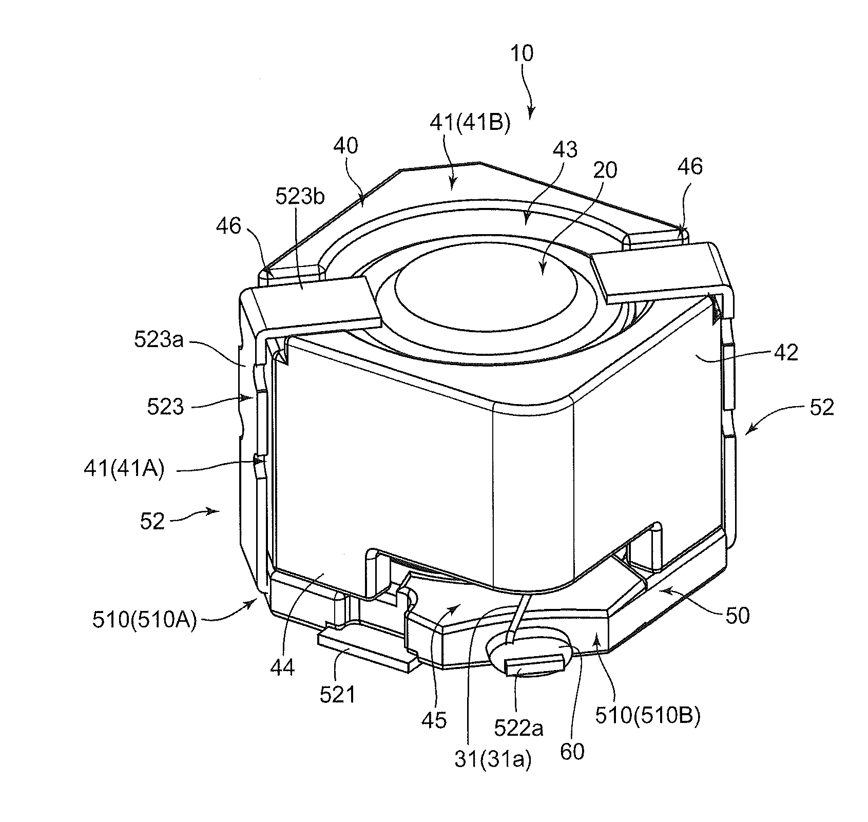
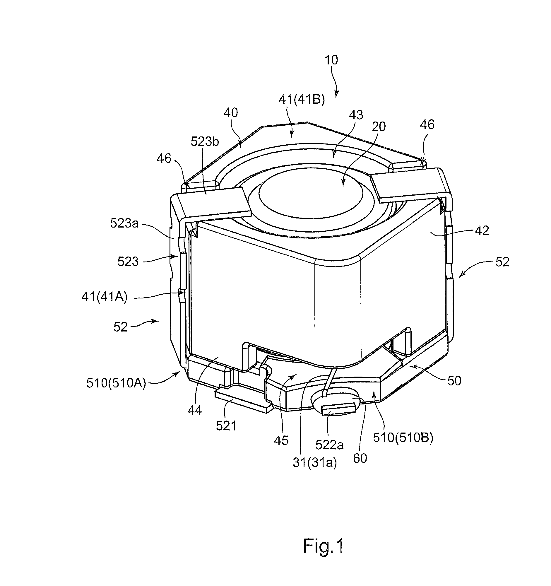
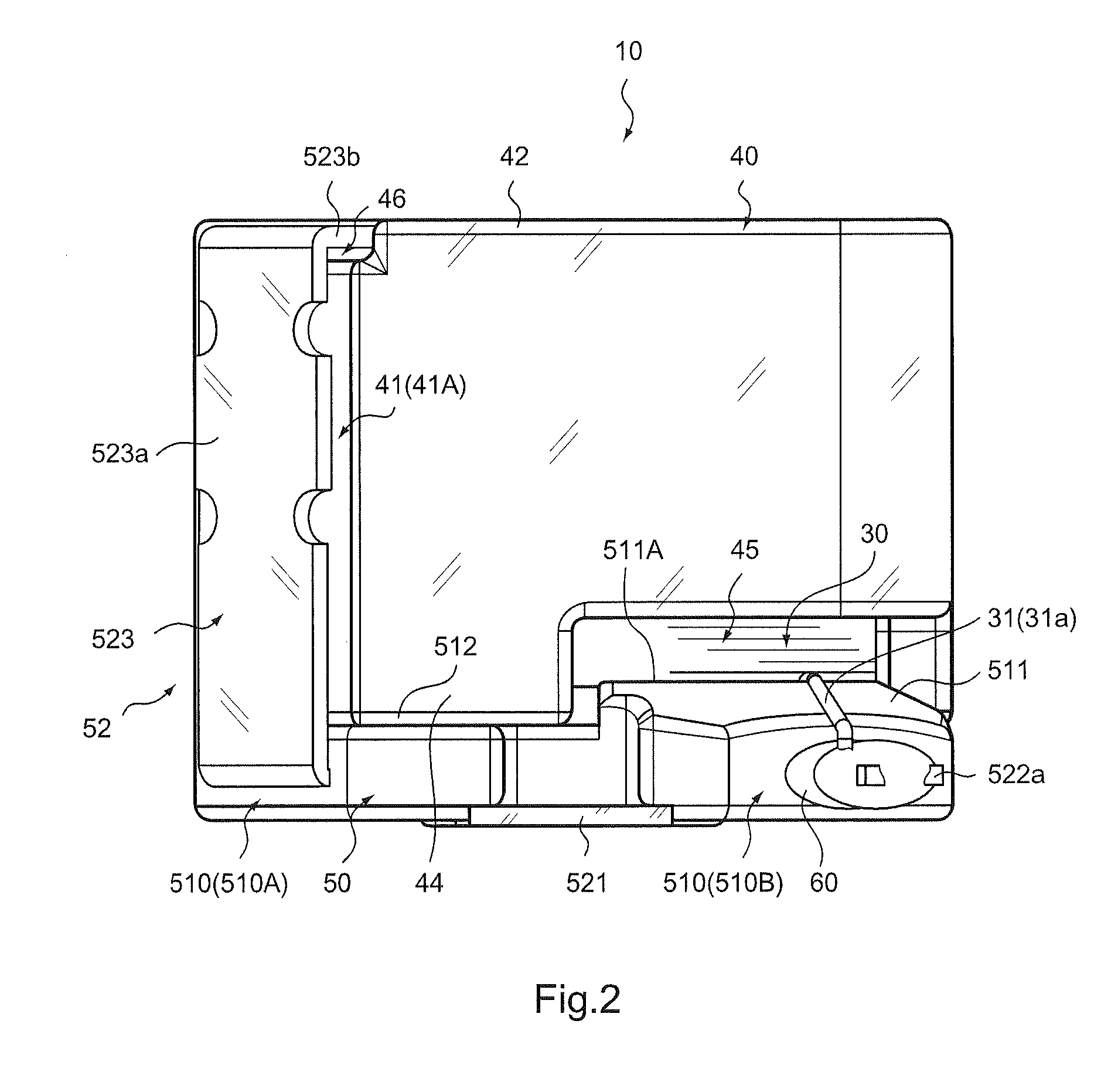
[0060]In the foregoing, the magnetic element 10 according to one embodiment of the present invention has been described, but the present invention can be modified in various other ways. This will be described below.

[0061]In the above-described embodiment, the drum core 20 is used as a first core member. However, the first core member is not limited to the drum core 20. For example, the first core member may be formed of two core members, a T-shaped core and a disc-shaped core. Further, in the above-described embodiment, the case where the ring core 40 is used as a second core member is described. However, the second core member is not limited to the ring core 40. For example, the second core member may be formed by butting semi-annular core members. Further, as the second core member, a pot core having a bottom and a substantially U-shaped cross section may be used. When the pot core is used as the second core member, it is preferred that a T-shaped core be used as the first core me...


PUM


Abstract

A magnetic element may include a first core member, a second core member facing the first core member along an entire outer periphery thereof, a coil, and a base shaped body on which the first core member and the second core member are placed. The base shaped body is provided with a base member and a terminal member, and the terminal member is provided with a binding terminal part, which projects outward in a first corner part of the base member and projects from the base member on a side lower than a portion of a winding frame part side of one flange part. The second core member is provided with a cutout part at a portion corresponding to the first corner part of the base member for allowing insertion of an end drawn out from the winding frame part in a state of not contacting the second core member.

Description

BACKGROUND OF THE INVENTION[0001]1. Field of the Invention[0002]The present invention relates to a magnetic element.[0003]2. Description of the Related Art[0004]Among magnetic elements, there exists a type having a drum core, a spacer, and a ring core as described in Patent Document 1. In such a structure disclosed in Patent Document 1, a terminal is disposed on an outer peripheral side of the ring core, and an end of a lead wire is soldered to this terminal.[0005][Patent Document 1] Japanese Patent Application Laid-open No. 2008-108944[0006]The magnetic element disclosed in Patent Document 1 has a structure in which the end of the lead wire contacts an edge existing in a surrounding area of a drawing portion of a large flange part, and moreover, the end of the lead wire contacts edges of the spacer and the ring core. However, when the end of the lead wire contacts edges of such a core and a spacer, the lead wire may break especially when the magnetic element is used in an environme...

Claims


Application Information

Patent Timeline
IPC IPC(8): H01F5/04
CPCH01F17/045H01F27/306H01F27/292
Inventor NISHINO, TATSUMIONO, MASAHIKO
Owner SUMIDA CORP
Why Eureka
Try Eureka