Permanent Magnets Array for Planar Magnetron

a permanent magnet array and planar magnetron technology, applied in the field of permanent magnet arrays, can solve the problems of non-uniform distribution of the magnetic field pattern formed by the magnet array, magnetic energy loss in the fe plate, and the magnetic field strength strength at the target surface is reduced, so as to achieve high magnetic flux density, reduce the effect of magnetic flux loss and reinforce the magnetic field

Inactive Publication Date: 2012-05-17
PLASMA INNOVATIONS
View PDF0 Cites 12 Cited by
  • Summary
  • Abstract
  • Description
  • Claims
  • Application Information

AI Technical Summary

Benefits of technology

[0012]The present invention includes permanent magnets array that embodied in a sputtering magnetron. A permanent magnets array for use in a planar magnetron in which magnets in magnet-segments are arranged in a Halbach array, i.e. with their magnetization directions alternating in directions perpendicular with each other. The magnet-segments are closely packed to form different shapes, such as heart, square, circular . . . , in a Halbach array style, which leads to minimum magnetic flux loss. Such arrangement of

Problems solved by technology

However, there are several issues with planar magnetron design of prior art.1. Those magnet pairs are arranged separately.
This causes not only the leaking of the magnetic flux and existence of fringing flux which reduce the magnetic field strength at the target surface, but most importantly, introducing non-uniform distribution of the magnetic fi

Method used


Image

  • Permanent Magnets Array for Planar Magnetron
  • Permanent Magnets Array for Planar Magnetron
  • Permanent Magnets Array for Planar Magnetron

Examples


Embodiment Construction

[0023]The following description is provided in the context of particular applications and the details, to enable any person skilled in the art to make and use the invention. However, for those skilled in the art, it is apparent that various modifications to the embodiments shown can be practiced with the generic principles defined here, and without departing the spirit and scope of this invention. Thus, the present invention is not intended to be limited to the embodiments shown, but is to be accorded the widest scope consistent with the principles, features and teachings disclosed here.

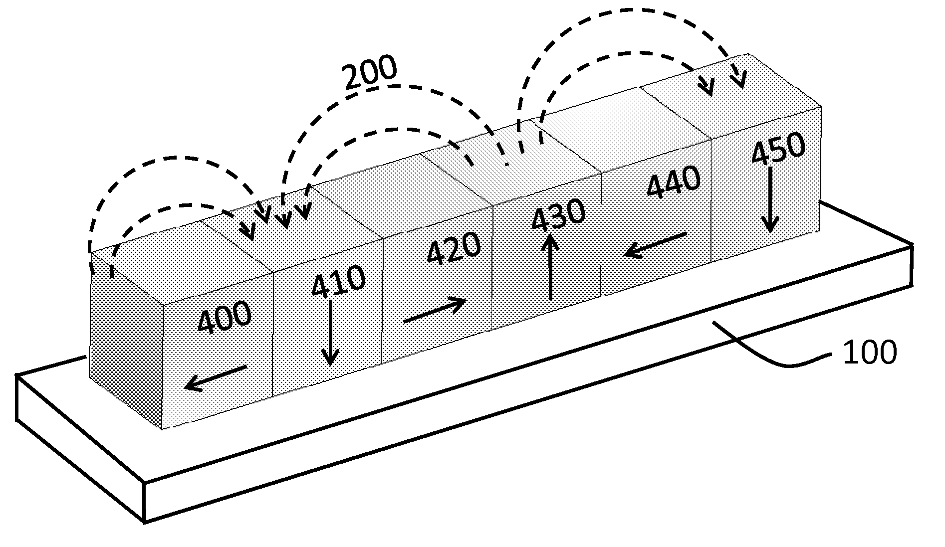
[0024]The present invention relates to a configuration of a dipole permanent magnet structure for generating an external magnetic fields which can be embodied in a sputtering magnetron for use in a magnetron sputtering system.

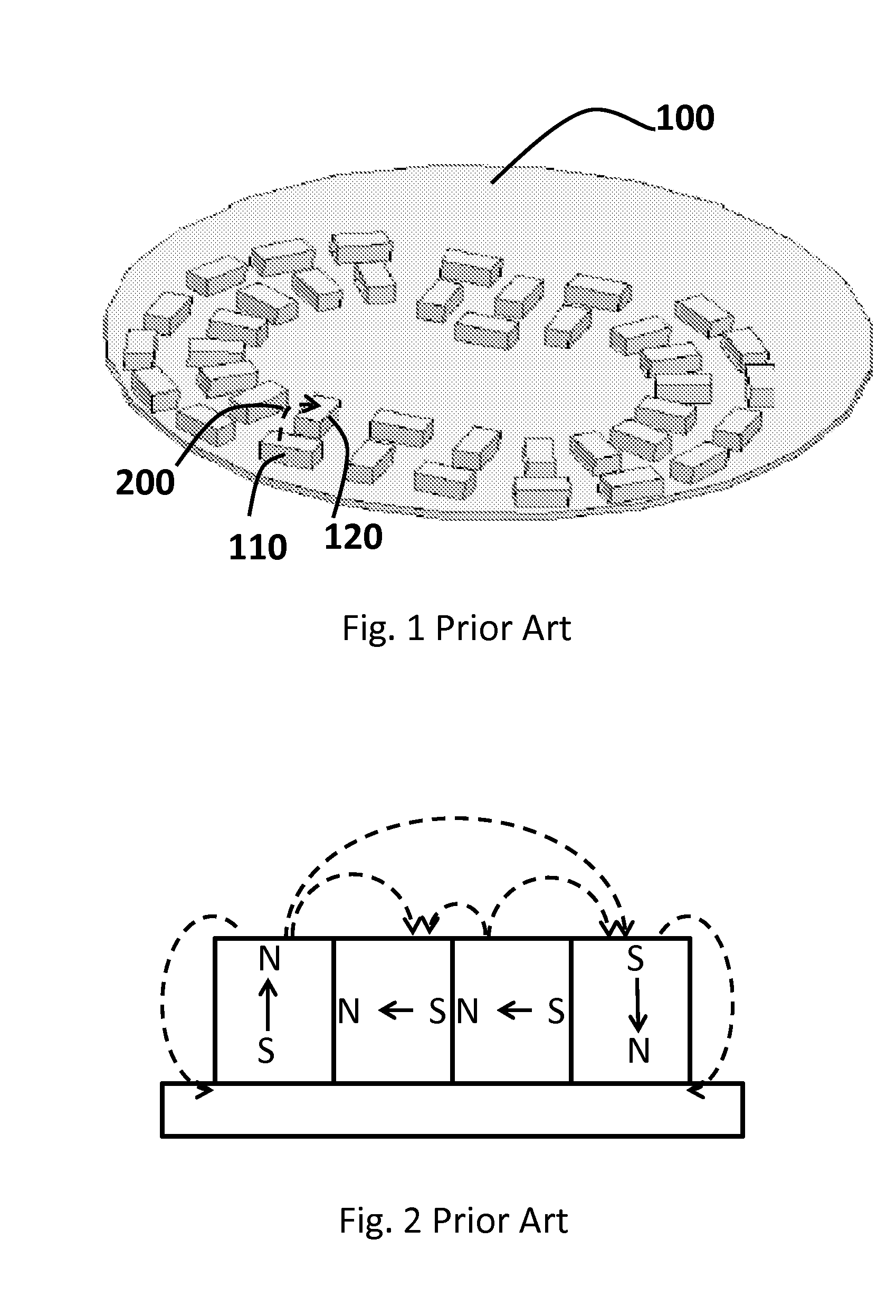
[0025]With reference to FIG. 1, a prior art dipole magnetic structure that may be embodied in a rotating magnetron used in a sputtering system is shown. The structure is compose...


PUM


Abstract

Permanent magnets array for use in a planar magnetron in which magnets in a magnet-segment is arranged in a Halbach array with their magnetization directions alternating in directions perpendicular with each other. The magnet-segments are closely packed to form different shapes, such as heart, square, circular . . . , in a Halbach Array style, which leads to minimum magnetic flux loss. Such arrangement of permanent magnets will also reinforce the magnetic field on one side of the array while cancel the field to near zero on the other side. The reinforced field strength is twice as large on the side on which the flux is confined. The permanent magnets arrangement and the resulting stationary and/or rotating planar magnetron, provides the high magnetic flux density and uniform flux distribution need to penetrate thick sputtering target, and increased not only the target usage, but also the usable the target life time.

Description

REFERENCE CITEDUS patent Documents[0001]4,622,122November 1986Richard F. Landau204 / 2984,872,964October 1989Masafumi Suzuki et al.204 / 2985,262,028November 1993Barry W. Manley204 / 192.125,865,970February 1999Richard Stelter et al.204 / 298.196,159,351December 2000Hussain J'Afer et al.204 / 298.196,183,614 B1February 2001Jianming Fu et al.204 / 298.27,182,843 B2February 2007Richard Stelter at al.204 / 192.27,223,322 B2May 2007Mark A. Bernick204 / 192.12FIELD OF INVENTION[0002]This present invention relates to permanent magnets array, and more specifically to permanent magnets array that can be used in a sputtering magnetron to create a magnetic field that passing through a target material for sputtering process.BACKGROUND ART[0003]Sputtering is the most widely used method for deposit thin film materials in the manufacturing of semiconductor and other microelectronic devices. Sputtering basically is glow discharge between a cathode and anode in a vacuum. In the process, an inert gas, such as Ar, i...

Claims


Application Information

Patent Timeline
IPC IPC(8): H01F7/02
CPCH01J37/3452H01F7/0278
Inventor TANG, YUNJUNSUN, YICHENG
Owner PLASMA INNOVATIONS
Why Eureka
Try Eureka