Solid dye resonator, and solid dye laser handpiece comprising same

Active Publication Date: 2012-05-17
LUTRONIC
View PDF3 Cites 7 Cited by
  • Summary
  • Abstract
  • Description
  • Claims
  • Application Information

AI Technical Summary

Benefits of technology

[0018]The solid dye resonator and the solid dye handpiece laser including the same according to the present invention having the above construction have the following effects.
[0019]First, there is an effect that the life span of a solid dye can be significantly extended and the pulse repetition rate can be increased by rotating the solid dye using the driving motor so that a position where pumping light is irradiated is varied (i.e., the pumping light is made not to be continuously irradiated to one place).
[0020]Second, there is an effect that rotational control is facilitated by constructing a solid dye in a disk form instead of a conventional cylindrical form.
[0021]Third, there is an effect that the life span of a solid dye can be further extended and the pulse repetition rate can be further increased by controlling the rotation of the driving motor (i.e., a driving source for rotating the solid dye) according to a pulse repetition rate set by a user.

Problems solved by technology

Conventional solid dye lasers, including Utility Model Application No. 2003-0037805 entitled “solid dye handpiece laser”, however, had the following problems.
The input energy of lasers is not fully converted into output energy, and most of the amount of the input energy not converted is converted into heat and consumed.
A conventional solid dye laser was problematic in that the life span of a solid dye was short and the pulse repetition rate Hz was low because the solid dye had a cylindrical shape and pumping light incident on a solid dye medium was irradiated to an always fixed position (i.e., one place).
That is, in case of the conventional solid dye laser, if the conventional solid dye laser is used for a long time, a surface of the solid dye is damaged by heat or dyes within the solid dye are quickly broken because a position on which the pumping light is incident is always constant.

Method used


Image

  • Solid dye resonator, and solid dye laser handpiece comprising same
  • Solid dye resonator, and solid dye laser handpiece comprising same
  • Solid dye resonator, and solid dye laser handpiece comprising same

Examples


Embodiment Construction

[0026]Preferred embodiments of a solid dye resonator and a solid dye handpiece laser including the same according to the present invention are described in detail on the basis of the accompanying drawings.

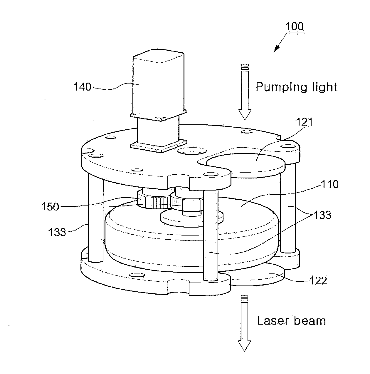
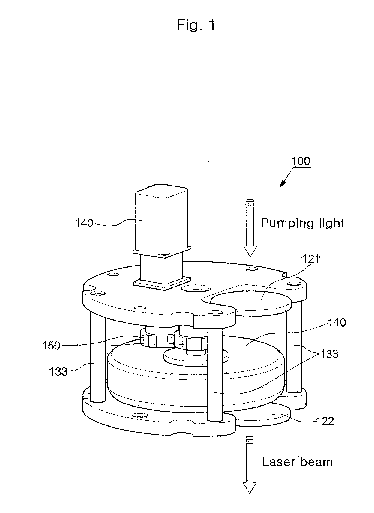
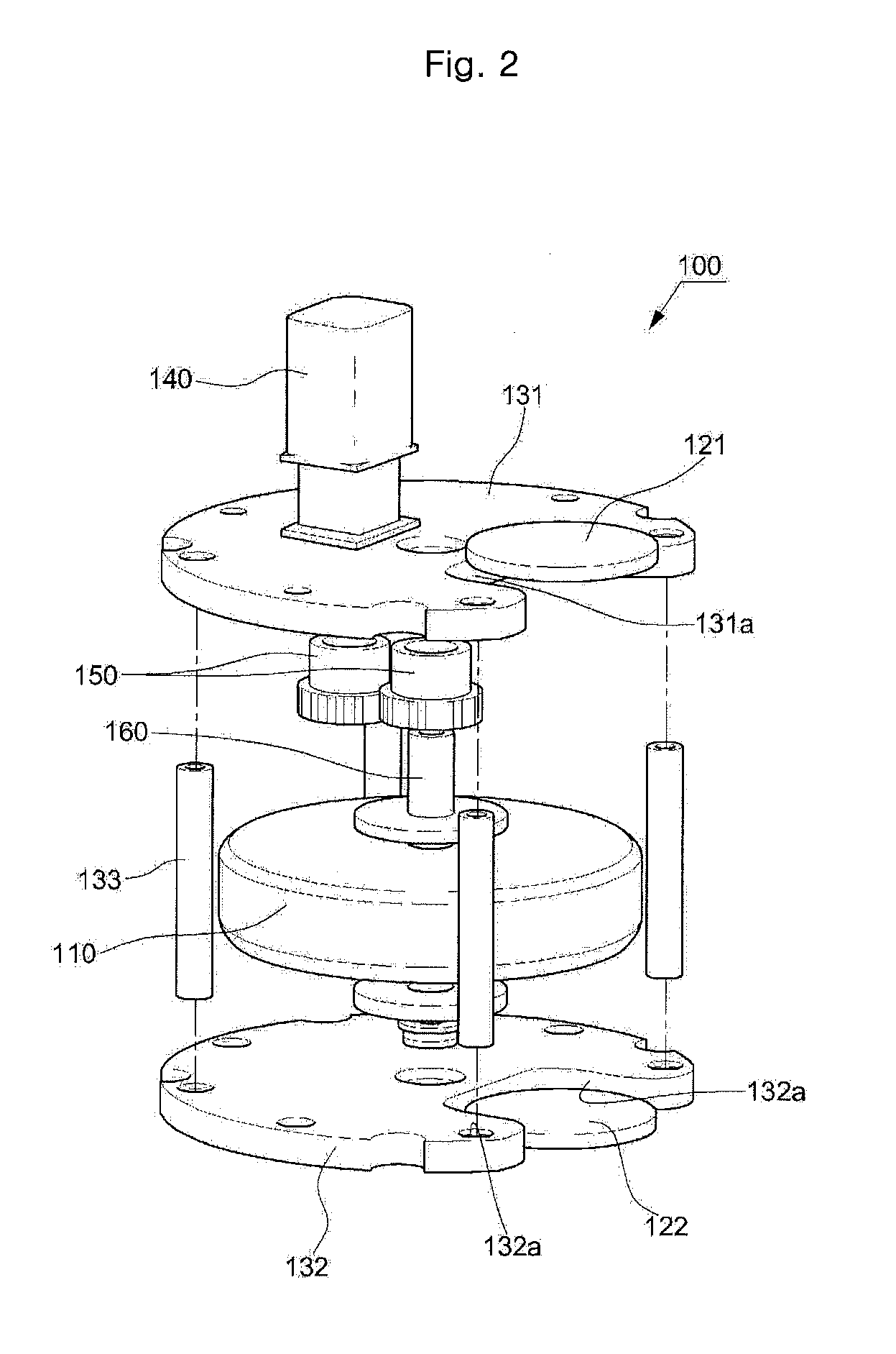
[0027]FIG. 1 is a perspective view of the solid dye resonator according to an embodiment of the present invention, FIG. 2 is an exploded perspective view of FIG. 1, and FIG. 3 is a block construction diagram for controlling a driving motor according to the pulse repetition rate in the solid dye resonator according to the embodiment of the present invention.

[0028]As shown in FIGS. 1 to 3, in the solid dye resonator 100 according to the embodiment of the present invention, including a solid dye 110 (i.e., a laser gain medium) configured to oscillate a laser wavelength by absorbing input pumping light, a high-reflection mirror 121 spaced apart from one side of the solid dye 110 and configured to transmit the pumping light toward the solid dye 110 and to reflect the light oscillated fr...


PUM


Abstract

The present invention relates to a solid dye resonator, and to a solid dye laser hand piece comprising same. The solid dye resonator comprises: solid dye; a high-reflection mirror; an output coupler; a first mounting plate on which the high-reflection mirror is mounted; a second mounting plate which is spaced apart from the first mounting plate and which has a surface on which the output coupler is mounted; a driving motor mounted on the first mounting plate, such that a motor shaft is directed toward the second mounting plate; and a rotary shaft interposed between the first mounting plate and the second mounting plate, and connected to the motor shaft of the driving motor such that the rotary shaft interlockingly rotates with the rotation of the driving motor.

Description

TECHNICAL FIELD [0001]The present invention relates to a solid dye resonator and, more particularly, to a solid dye resonator and a solid dye handpiece laser including the same, in which a solid dye is rotated by using a driving motor so that a position where pumping light is irradiated is varied (Le., the pumping light is made not to be continuously irradiated to one place), thereby being suitable for significantly extending the life span of a solid dye and increasing the pulse repetition rate.BACKGROUND ART [0002]In general, a solid dye is a laser oscillation medium solidified by injecting dye into plastic or glass in the existing liquid dye laser.[0003]Here, the dye is not dye used in a common life, but is a specific dye enabling laser oscillation.[0004]Furthermore, an apparatus in which a resonator employing the solid dye is included in the hand piece of a medical laser device is called a solid dye handpiece laser. That is, the solid dye handpiece laser is a laser reduced in siz...

Claims


Application Information

Patent Timeline
IPC IPC(8): H01S3/20
CPCA61N5/067H01S3/025H01S3/1026H01S3/168
Inventor LEE, HEE CHUL
Owner LUTRONIC
Why Eureka
Try Eureka