
Regulating element

a technology of regulating element and clamping system, which is applied in the direction of manufacturing tools, shaping cutters, reaming devices, etc., can solve the problem that the angle cannot be produced with infinite accuracy

Active Publication Date: 2012-05-17
KENNAMETAL INC
View PDF3 Cites 1 Cited by
  • Summary
  • Abstract
  • Description
  • Claims
  • Application Information

AI Technical Summary

Benefits of technology

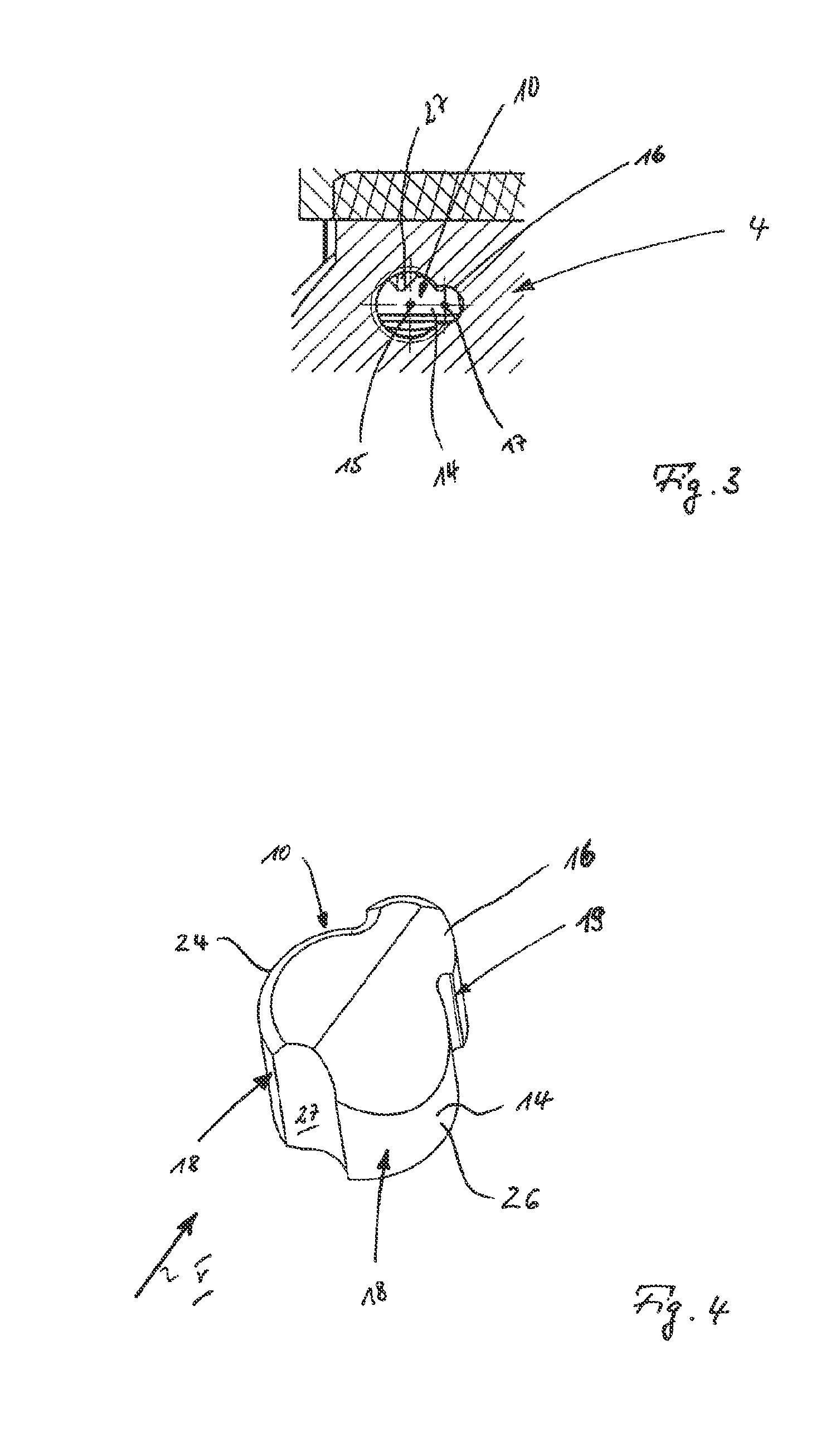
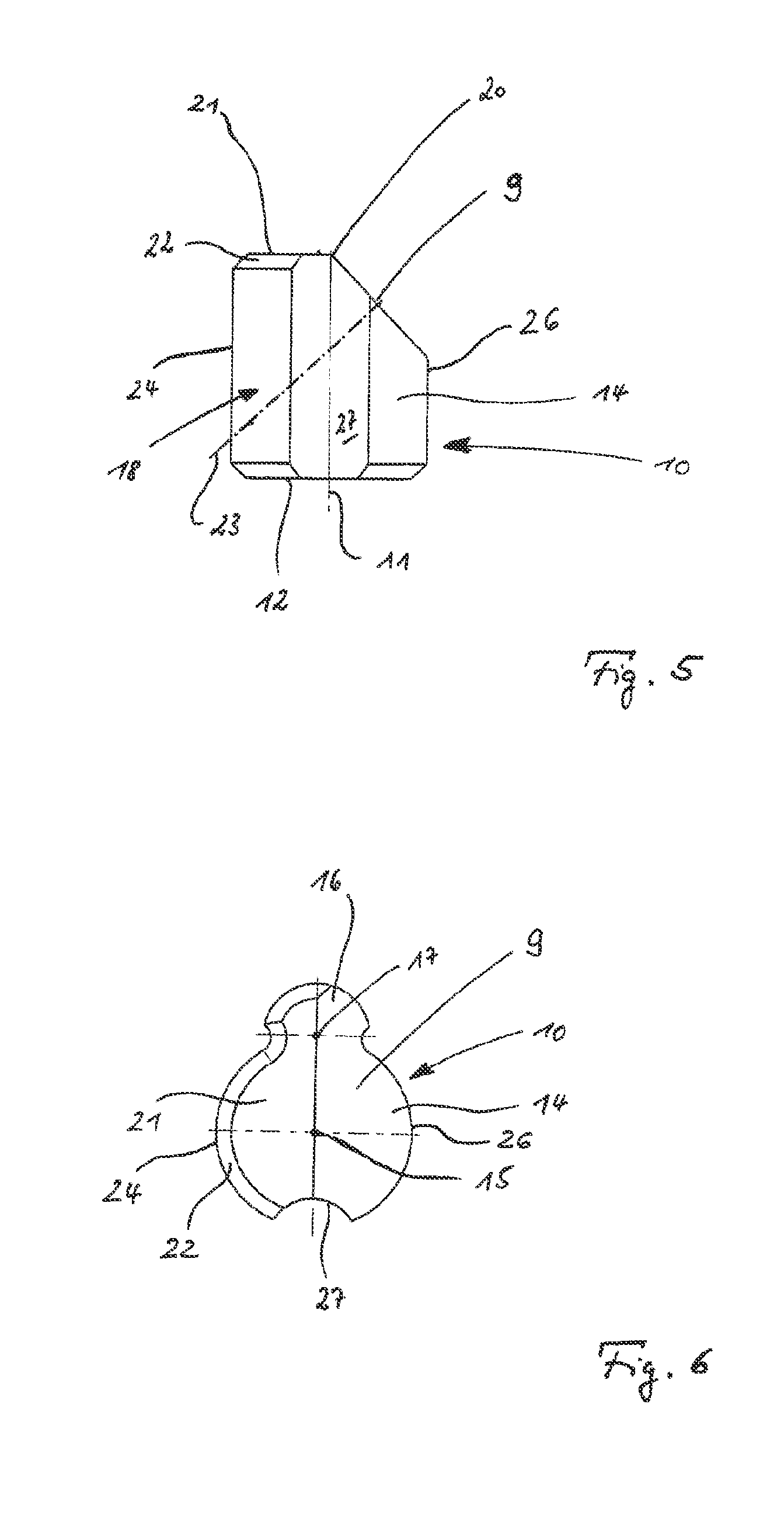
[0005]To avoid the undesirable rotatability, initial consideration should be given to a prismatic, in particular square, design of the basic body of the setting element. The risk of the undesirable rotation would then be effectively removed. However, a prismatic cross-sectional shape has the disadvantage that the bearing surfaces bear only linearly or even only in a point-like manner against the respective mating surfaces in the basic body on the one hand and against the cutting-body rear wall on the other hand, because the respective angles cannot be produced with infinite accuracy. In this way, the automatic orientation, desired with the invention, of the setting element in its guide for flat, in particular planar, bearing of the active surface against the associated rear wall of the cutting body would no longer be ensured. The achievement of the object therefore consists in substantially retaining the cylindrical outer contour of the setting element and in altering only a small region of the outer contour of the setting element in such a way that the undesirable rotatability is removed. The cylindrical basic body of the setting element has a circular, that is to say rotationally symmetrical, cross-sectional shape. Asymmetry of the cross section of the basic body serves as anti-rotation locking means, said asymmetry being integrally formed on or in the basic body only over a small angular range of the circular cross section. This contour deviating from the cylindrical shape of the basic body can be integrally formed both on and in the basic body. As a result of the modification of the basic body according to the invention, while at the same time retaining the cylindrical basic shape, the undesirable rotatability of the setting element is thus removed, while continuing to maintain the automatic orientation of the setting element in its guide. The rotationally locked setting element can still be rotated within a small angular range. The setting element can be automatically oriented both relative to the cutting-body rear wall active as bearing surface and relative to the inner walls of the guide in the basic body.
[0010]The development of the invention with a partly cylindrical body which is integrally formed on the cylindrical basic body is advantageous from the production point of view and is therefore inventive on its own. In this way, the setting element is given the outline form of two overlapping circle segments, that is to say substantially the cross-sectional shape of the Arabic numeral 8. According to the invention, the one circle segment forming the actual basic body of the setting element is markedly larger than the other circle segment forming the contour. From the production point of view, this variant has the advantage that first of all the locating hole for the contour can be drilled using a first small drill and then the actual guide for the setting element can be drilled in the same setup using a large drill. For the sake of completeness, it should be noted that this inventive advantage from the production point of view can also be realized with the slot-key combination, already described above, as contour.

Problems solved by technology

However, a prismatic cross-sectional shape has the disadvantage that the bearing surfaces bear only linearly or even only in a point-like manner against the respective mating surfaces in the basic body on the one hand and against the cutting-body rear wall on the other hand, because the respective angles cannot be produced with infinite accuracy.

Method used


Image

  • Regulating element
  • Regulating element
  • Regulating element

Examples


Embodiment Construction

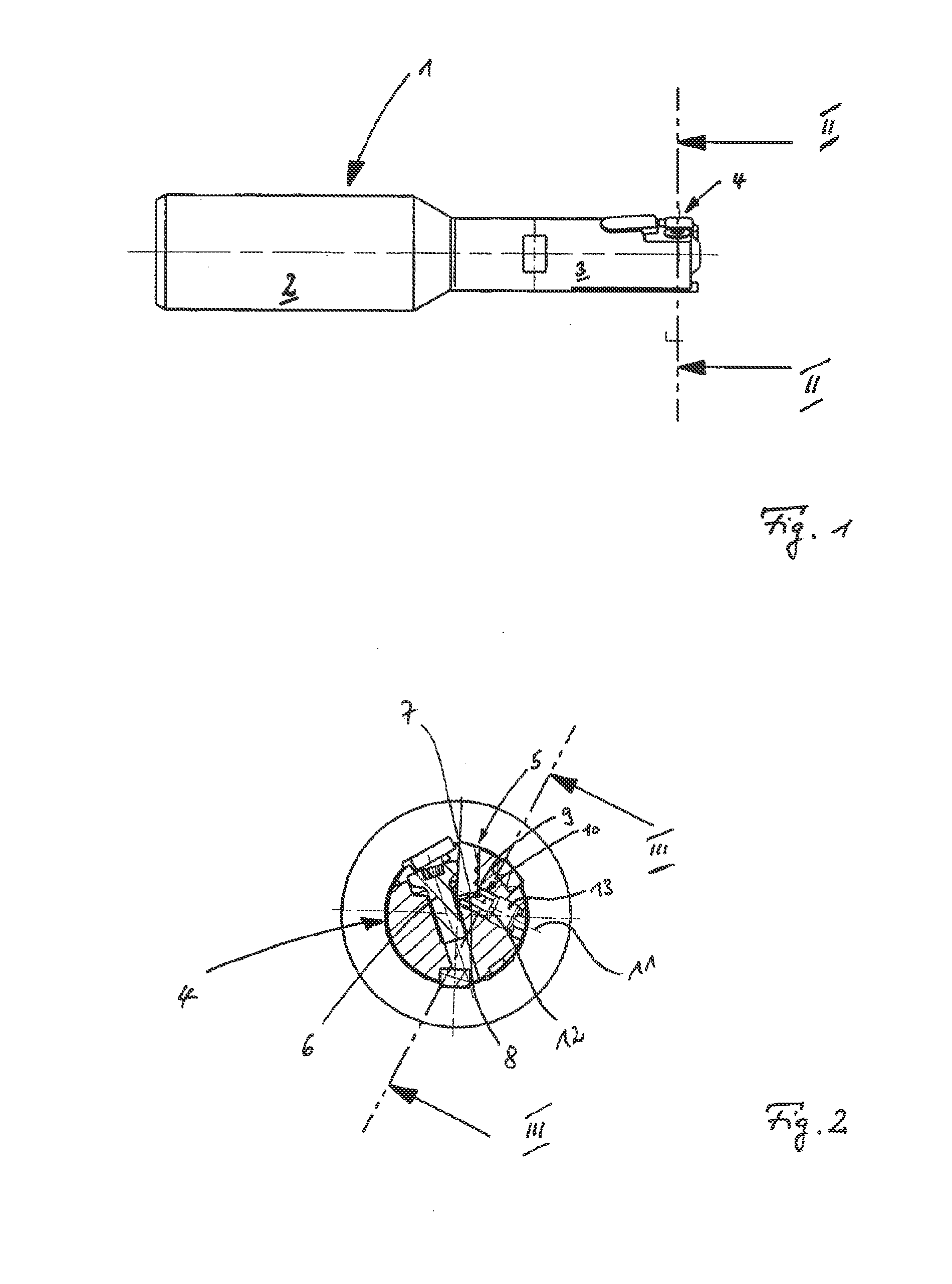
[0019]The rotating cutting tool 1 shown in FIG. 1 in its side view has a chucking region 2 for chucking the cutting tool 1 in the chuck of a machine tool and a tool receptacle region 3, on the end of which the tool seat 4 is formed. The details of the tool seat 4 are described in more detail with reference to FIG. 2. In principle, it is also possible to use the construction of the tool seat known from the prior art WO 2007 / 088353 A1—FIG. 5.

[0020]The cutting body 5 configured as a cutting insert is clamped in the tool seat 4 by means of a clamping screw 6. The cutting body 5 has a cutting edge 7, projecting from the tool seat 4, and a cutting-body rear wall 8. In the exemplary embodiment, the active surface 9 of the setting element 10 designed as a setting wedge bears in a planar and flush manner against the cutting-body rear wall 8.

[0021]The setting element 10 is acted upon by a headless screw 13 from its free end 12 remote from the active surface 9 in the direction of the center lo...


PUM

PropertyMeasurementUnit
angleaaaaaaaaaa
cylindrical shapeaaaaaaaaaa
lengthaaaaaaaaaa

Abstract

The invention relates to a regulating element (10) for a cutting member (5) clamped in a tool seat (4) of a cutting tool (1), comprising a cylindrical basic body (14), and an active surface (9) impacting the cutting member (5) at a face side (20) when in a mounted state, having a contour (16) deviating from the cylindrical shape at the cylinder sleeve of the basic body (14) as anti-twist protection for the regulating element (10).

Description

[0001]The invention relates to a setting element for a cutting body clamped in a tool seat of a cutting tool and to a cutting tool comprising a cutting body set precisely by a setting element.BACKGROUND OF THE INVENTION[0002]WO 2007 / 088353 A1 discloses a tool clamping system which has a cutting body configured as a cutting insert, a clamping screw clamping the cutting insert in the tool seat, and a setting element for the precision setting of the cutting insert. In this case, the setting element is configured as a longitudinally displaceable setting wedge. The setting wedge has an active surface which runs obliquely relative to the basic body and which applies pressure to the cutting-body rear wall of the cutting insert, said cutting-body rear wall being remote from the active cutting edge of the cutting insert. The basic body of the setting element is of cylindrical configuration. The cylindrical configuration of the basic body has the advantage that the basic body of the setting e...

Claims


Application Information

Patent Timeline
Patent Type & Authority Applications(United States)
IPC IPC(8): B23D77/02B23B27/16
CPCB23B2260/146B23D77/042B23D77/044Y10T407/1912Y10T407/28Y10T408/858Y10T407/2282B23C3/00B23D75/00B23D77/04
Inventor HACKER, MICHAELMANNER, HEINRICHSPICHTINGER, XAVER
Owner KENNAMETAL INC
Learn More