Machining head for machine tool

a technology of machining head and machine tool, which is applied in the direction of manufacturing tools, driving apparatus, metal-working machine components, etc., can solve the problems of reducing the work space increasing the size of the machine tool, and reducing the overall size so as to prevent the dimension of the machining head, prevent the size increase of the machine tool and deterioration of the machining accuracy

Inactive Publication Date: 2012-05-17
TSUDAKOMA KOGYO KK
View PDF20 Cites 8 Cited by
  • Summary
  • Abstract
  • Description
  • Claims
  • Application Information

AI Technical Summary

Benefits of technology

[0013]According to the machining head for the machine tool in the present invention, the bearing for rotatably supporting the support shaft is disposed within the range occupied by the DD motor in the axial direction of the support shaft. In addition, the rotary joint is disposed within the motor rotor of the DD motor in the radial direction thereof. Accordingly, this prevents the dimension of the machining head in the axial direction of the support shaft from increasing, thereby avoiding an increase in the overall size of the machining head. This advantageously prevents size increase of the machine tool and deterioration of the machining accuracy.

Problems solved by technology

This results in a large dimension of the machining head in the axial direction of the support shaft, causing the machining head to be large in its overall size.
In the case of the double-housing machine tool described above, for example, a machining head having a large size will inevitably cause an increase in size of the machine tool to attain a sufficient movement range for the machining head or will limit the work space on the machine tool.
In addition, an increase in weight due to the size increase can hinder the movement of the machining head and thus cause an adverse effect on the workability.
Moreover, depending on the weight of the machining head, the cross beam can become bent, causing the machining accuracy to be deteriorated.

Method used


Image

  • Machining head for machine tool
  • Machining head for machine tool
  • Machining head for machine tool

Examples


first embodiment

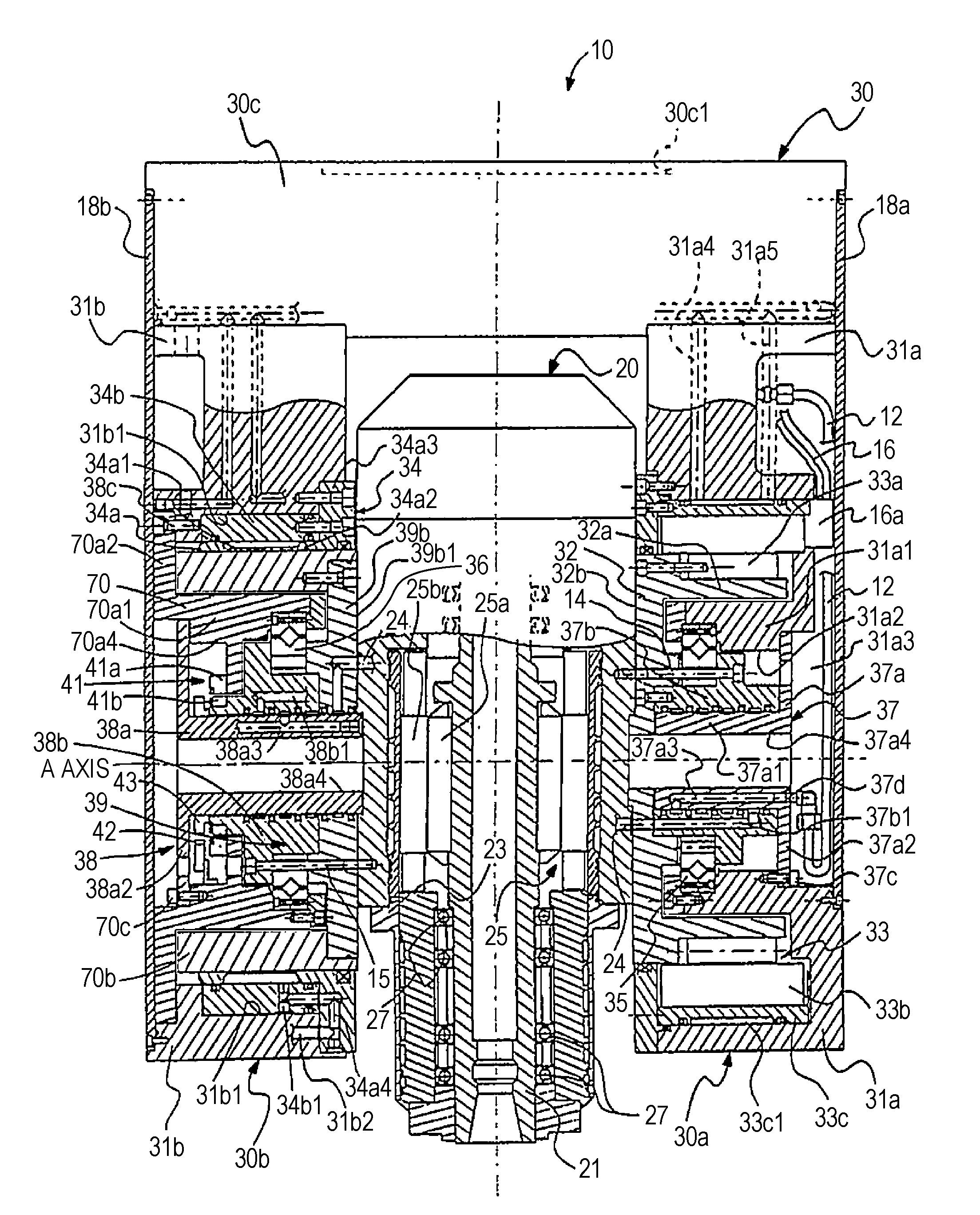
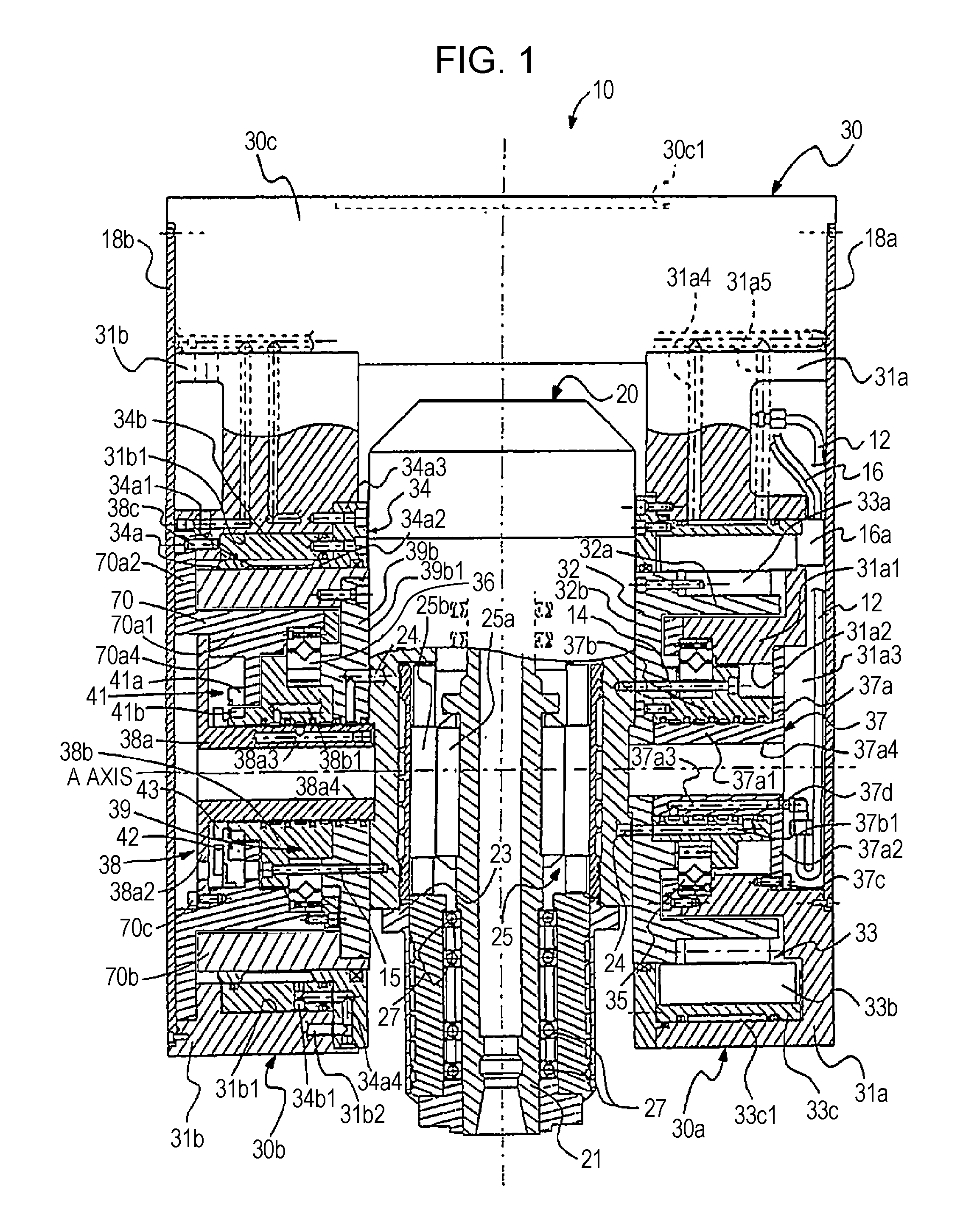
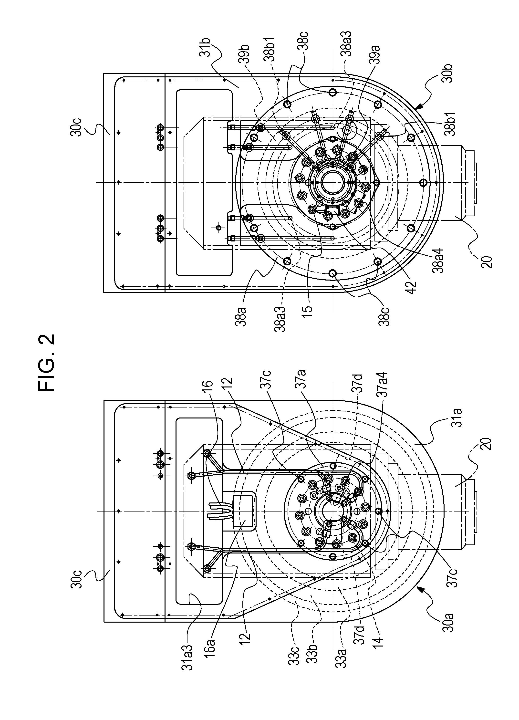
[0077]FIGS. 1 to 3 illustrate the present invention. A machining head 10 includes a spindle unit 20 having a spindle 21 to which a tool can be attached, a first support head component 30 that supports the spindle unit 20, and a second support head component 50 that supports the first support head component 30 (FIG. 3). The first support head component 30 (corresponding to a support head component according to the present invention) has the shape of a fork in which a pair of leg segments 30a, 30b is joined to a supporting segment 30c. The spindle unit 20 is supported between the leg segments 30a, 30b. One of the leg segments 30a, 30b is provided with a DD motor 33 (corresponding to a drive motor according to the present invention) for rotating the spindle unit 20.

[0078]The spindle unit 20 is a spindle head having a drive motor 25 built therein, and the built-in drive motor 25 rotates the spindle 21 at high speed.

[0079]A housing 23 of the spindle unit 20 has the spindle 21 extending t...

second embodiment

[0142]the present invention will now be described with reference to FIG. 6.

[0143]In the support head component (the first support head component 30) of the machining head according to the first embodiment of the present invention, only one of the leg segments of a pair for supporting the spindle unit 20 is provided with an index mechanism (DD motor) for rotating the spindle unit 20. In contrast, the second embodiment shown in FIG. 6 is characterized in that both leg segments of the support head component are provided with index mechanisms (DD motors), and that the present invention is applied to both index mechanisms.

[0144]The second embodiment shown in FIG. 6 differs from the first embodiment shown in FIG. 1 in that each bearing that rotatably supports the corresponding support shaft rotated by the corresponding DD motor is interposed between the distributor and the shaft that constitute the corresponding rotary joint. In other words, in contrast to the first embodiment in which th...


PUM

PropertyMeasurementUnit
speedaaaaaaaaaa
sizeaaaaaaaaaa
weightaaaaaaaaaa

Abstract

A machining head (10) for a machine tool includes a spindle unit (20) to which a tool is attachable and a support head component (30, 60) that includes an index mechanism for indexing an angular position of a spindle (21). The index mechanism includes a drive motor (33, 63) supported by a bearing (35, 65) within the housing (31a, 61) of the support head component (30, 60) and a rotary joint (37, 67) disposed concentrically with the bearing (35, 65) and the drive motor (33, 63). The bearing (35, 65) is disposed within a range occupied by the drive motor (33, 63) in an axial direction of a support shaft (32, 37b, 62, 67c), and the rotary joint (37, 67) is disposed within the drive motor (33, 63) in a radial direction thereof.

Description

TECHNICAL FIELD[0001]The present invention relates to machining heads for machine tools, and particularly, to a machining head equipped with an index mechanism, which is used in a compound processing machine (machine tool), such as a five-axis processing machine (that is, a processing machine capable of controlling five axes simultaneously) and a multi-face processing machine.Background Art[0002]FIG. 7 illustrates a double-housing machine tool (machining center) 1 as an example of a compound processing machine. The double-housing machine tool 1 includes left and right columns 2, 2 attached to a bed 4, a cross rail 6 movable vertically (in Z-axis direction) on the columns 2, 2, a saddle 7 movable horizontally (in Y-axis direction) on the cross rail 6, a ram 8 movable in the Z-axis direction on the saddle 7, and a table 5 movable in the front-back direction (in X-axis direction) on the bed 4. Furthermore, the ram 8 has a machining head 10 attached thereto, which includes a spindle uni...

Claims


Application Information

Patent Timeline
Patent Type & Authority Applications(United States)
IPC IPC(8): B23C1/12B23Q1/70
CPCB23Q1/0018B23Q1/5406Y10T409/307672B23Q2220/006B23Q2210/004B23Q1/70B23Q3/12B23Q5/04B23Q5/00
Inventor TATSUDA, YOSHINORI
Owner TSUDAKOMA KOGYO KK
Why Eureka
Try Eureka