Ratchet-type tensioner

a ratchet-type, tensioner technology, applied in the direction of belts/chains/gearings, mechanical instruments, belts/chains/gearings, etc., can solve the problems of inconvenient assembly of tensioner components, inability to maintain consistent engagement and faulty operation of the ratchet mechanism, and /b>524/b> on the piston rod, etc., to avoid wear and chipping of teeth, reduce the size of the tensioner

Inactive Publication Date: 2012-05-17
TSUBAKIMOTO CHAIN CO
View PDF8 Cites 4 Cited by
  • Summary
  • Abstract
  • Description
  • Claims
  • Application Information

AI Technical Summary

Benefits of technology

[0021]The movable plug is preferably formed with a blind, spring-receiving hole having an opening facing toward the spring retainer. The plug-biasing spring, which is preferably a coil spring under compression, extends into the blind, spring-receiving hole and protrudes through the opening thereof facing toward the spring retainer. Because the spring extends into a hole in the movable plug instead of engaging the end or fitting around the outer peripheral surface of the movable plug, the ratchet structure is simplified, and it becomes possible to reduce the size of the tensioner.
[0022]In a preferred embodiment of the tensioner, the rearward faces of the rack teeth of the plunger and the forward faces of the teeth of the movable plug have the same first inclination relative to the direction orthogonal to the direction of movement of the plunger. The forward faces of the rack teeth of the plunger and the rearward faces of the teeth of the movable plug can have the same second inclination relative to the orthogonal direction, and the angle of the first inclination is smaller than the angle of the second inclination. The relationship between the angles of the tooth faces allows the plunger of the tensioner to protrude smoothly during operation of an engine while blocking retraction of the plunger. However, the slope of the rearward facing teeth of the plunger and the cooperating forward-facing teeth of the movable plug can allow the plunger to move in the retracting direction when the load on the plunger becomes excessive, while avoiding the wear and chipping of teeth that occur in conventional ratchet tensioners, and while avoiding excessive impact on the plug-biasing spring.
[0023]If the angle of the first inclination is greater than zero, the rack teeth of the plunger and the teeth of the movable plug allow the plunger to be moved in the retracting direction when the net force exerted on the plunger in the retracting direction is greater than a predetermined force. Consequently, the tensioner, when used to maintain tension

Problems solved by technology

As a result, inconsistent engagement and faulty operation of the ratchet mechanism can occur, and the teeth 536 on the piston rod 524 are liable to be chipped.
The ability of the piston and plunger to rotate also opens the possibility of errors in assembly of the tensioner components both in manufacture and in maintenance of the tensioner.
Thus, excessive tension can cause seizing of the plunger, increased load on the chain, and excessive noise.
However,

Method used


Image

  • Ratchet-type tensioner
  • Ratchet-type tensioner
  • Ratchet-type tensioner

Examples


second embodiment

[0065]In a second embodiment illustrated in FIG. 11, parts corresponding to those in the above-described embodiment are designated by reference numbers that exceed the numbers of the parts in the above-described embodiment by 100.

[0066]In this second embodiment, the movable plug 250 has an elliptical cross-section, and the hole (not shown) in which the plug slides in a direction orthogonal to the direction of movement of the plunger has a similar elliptical cross-section conforming to that of the movable plug. Consequently, the plug can slide in the hole, but cannot rotate. Thus the teeth 251 are maintained in alignment with the rack teeth on the plunger even if the tensioner is subject to vibration. The alignment of the teeth of the movable plug with the rack teeth on the plunger is maintained by the elliptical shapes of the movable plug and the hole in which it slides, and is independent of the engagement of the teeth. Moreover the teeth engage one another accurately over the full...

first embodiment

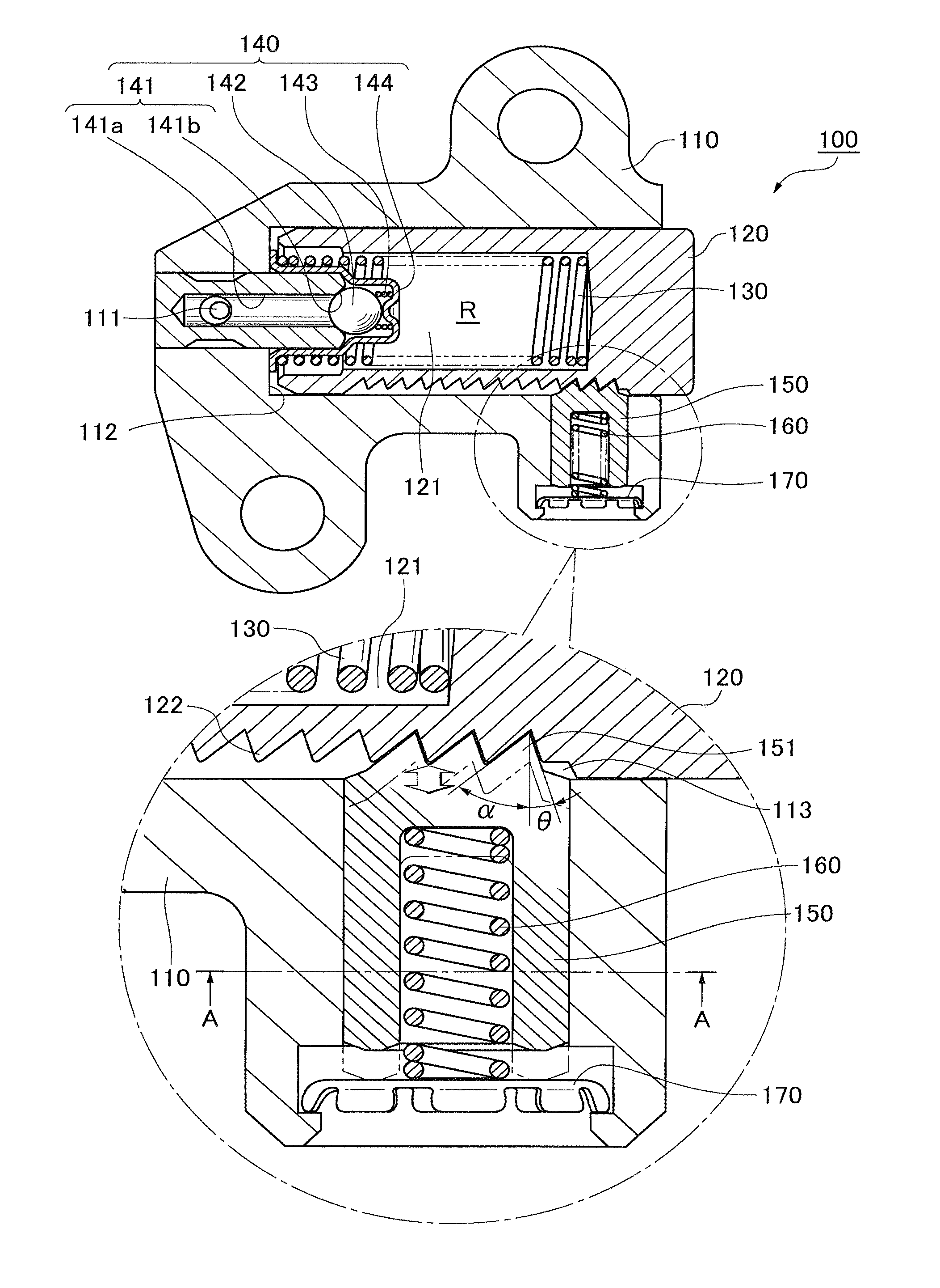
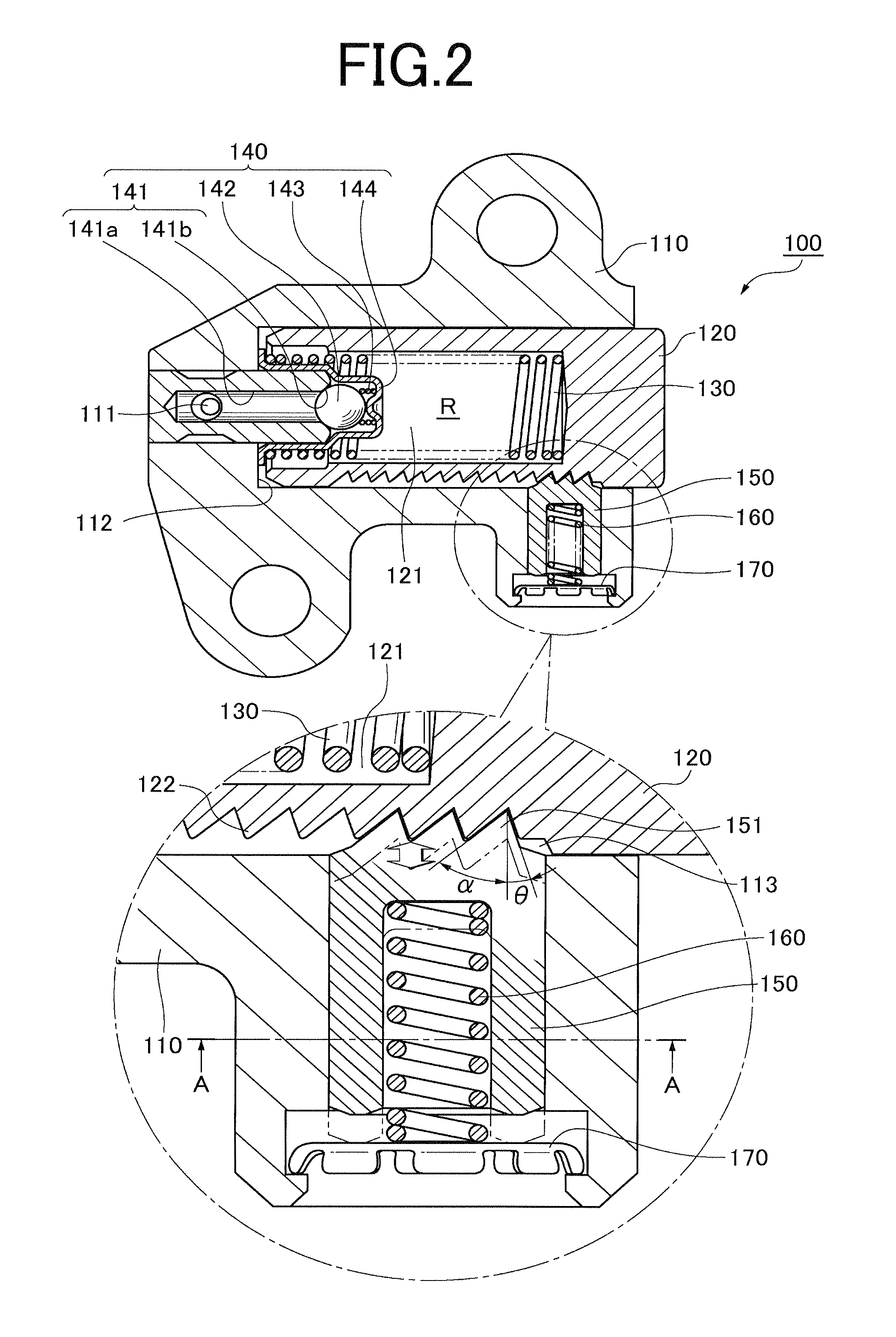
[0067]Here, as in the first embodiment, the length W of the movable plug is greater than its maximum lateral dimension as shown in FIG. 11. Consequently, inclination of the movable plug due to excessive load is reduced.

[0068]Three ratchet teeth 251, having a uniform pitch and having the same tooth height, are provided on the plunger-facing end of the movable plug 250 in order to engage with rack teeth on the side of the plunger while dispersing the load applied to the ratchet teeth by the plunger.

[0069]The ratchet-type tensioner of the second embodiment exhibits the same reliable and stable operation as exhibited by the tensioner of the first embodiment. With the second embodiment, it is possible to eliminate faulty operation of the ratchet mechanism by avoiding twisting of the movable plug. Manufacture of the tensioner in accordance with the second embodiment is simplified because the precision machining required to produce a spline on the movable plug and a mating groove in the ho...


PUM


Abstract

In a ratchet tensioner, rack teeth on a plunger are engaged by ratchet teeth on one end of a movable plug that slides in a hole in the tensioner housing along a direction orthogonal of the direction of movement of the plunger. The movable plug is prevented from rotating in the hole in which it slides so that the ratchet teeth engage the rack teeth on the plunger smoothly and reliably.

Description

CROSS REFERENCE TO RELATED APPLICATIONS[0001]This application claims priority on the basis of Japanese patent application filed on Nov. 11, 2010. The disclosure of Japanese application 2010-252844, is hereby incorporated by reference.FIELD OF THE INVENTION[0002]The invention relates to a ratchet-type tensioner for applying a tensioning force to a timing chain used for driving one or more camshafts, and sometimes other mechanisms, in an engine.BACKGROUND OF THE INVENTION[0003]A typical ratchet-type tensioner includes a plunger slidable in a plunger-accommodating hole in a tensioner housing. An oil chamber is formed by the plunger and the housing. Tensioning force applied to a timing chain, both by a spring in the oil chamber and by oil supplied under pressure to the oil chamber from an external source, urges the plunger in the protruding direction,.[0004]A typical prior art ratchet-type tensioner 500 is disclosed in Japanese Utility Model No. 2559664 and illustrated in FIG. 12. In th...

Claims


Application Information

Patent Timeline
IPC IPC(8): F16H7/08
CPCF16H7/0848F16H2007/0853F16H2007/0812F16H2007/0806F16H7/08
Inventor YOSHIDA, OSAMUKUREMATSU, YUJIMAEDA, MUNEHIRO
Owner TSUBAKIMOTO CHAIN CO
Why Eureka
Try Eureka