Ultrasonic transducer and method of manufacturing the same
- Summary
- Abstract
- Description
- Claims
- Application Information
AI Technical Summary
Benefits of technology
Problems solved by technology
Method used
Image

Examples
embodiment 1
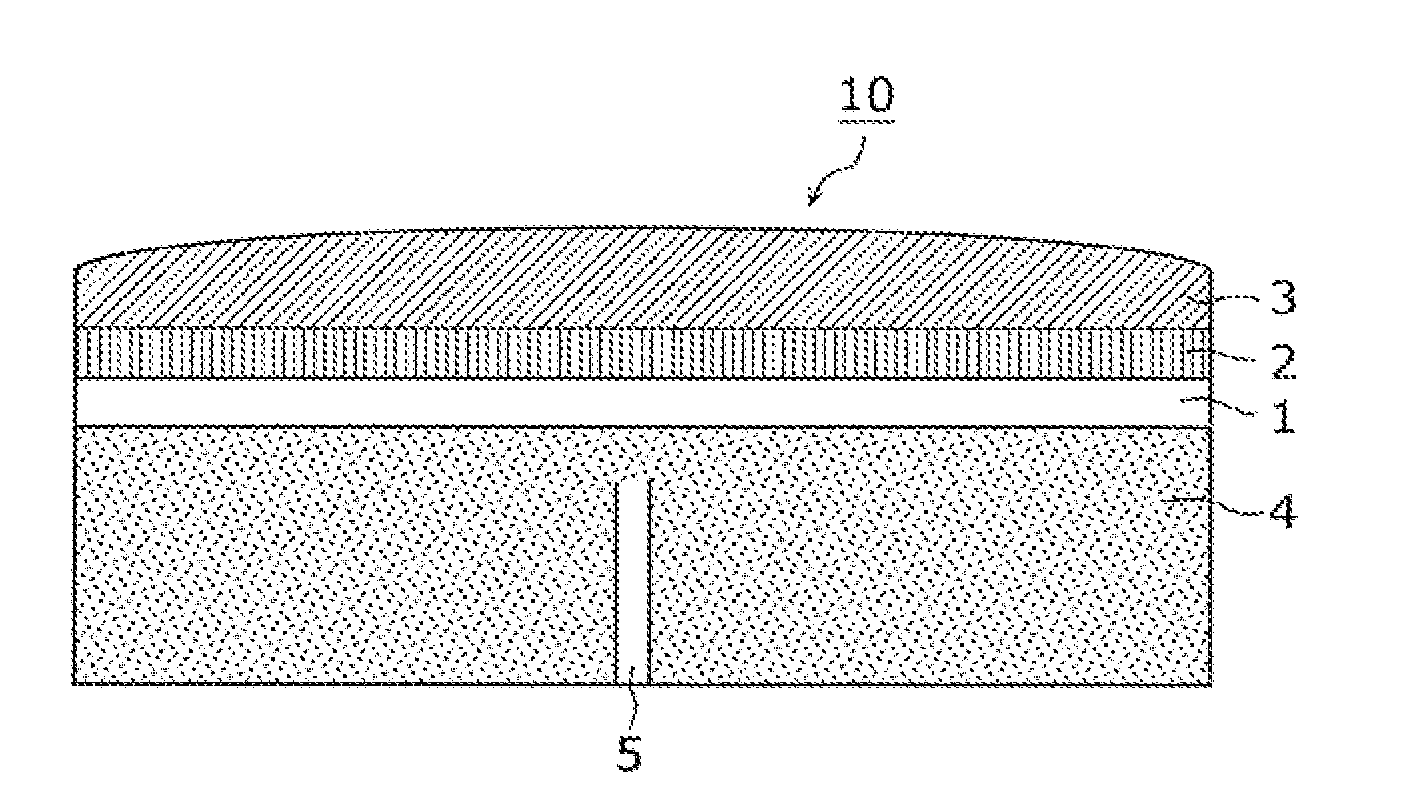
[0056]FIG. 3 is a cross-sectional view showing a structure of an ultrasonic transducer according to Embodiment 1 of the present invention. The ultrasonic transducer 10 shown in FIG. 3 includes a piezoelectric transducer 1, a matching layer 2, an acoustic lens 3, and a backing layer 4. In addition, as shown in FIG. 3, the ultrasonic transducer 10 includes an acoustic tube 5 that is formed in the backing layer 4.
[0057]The acoustic tube 5 is formed such that its width (w) is sufficiently small compared to the wavelength (λ) of the ultrasonic waves emitted from the piezoelectric transducer 1, and its length (Ln) causes direct waves of the ultrasonic waves and reflected waves of the ultrasonic waves to cancel out each other.
[0058]Here, the wavelength λ in the backing layer 4 may be obtained by Equation 1.
[Math.1]λ=Cf(Equation1)
[0059]For example, when it is assumed that the backing layer 4 is made of an epoxy resin and the piezoelectric transducer 1 emits the ultrasonic waves of f=5 MHz. ...
embodiment 2
[0063]Although Embodiment 1 has described an example where one acoustic tube is formed in a backing layer, the present invention is not limited to this. Embodiment 2 describes the case where a plurality of acoustic tubes is arranged in the backing layer.
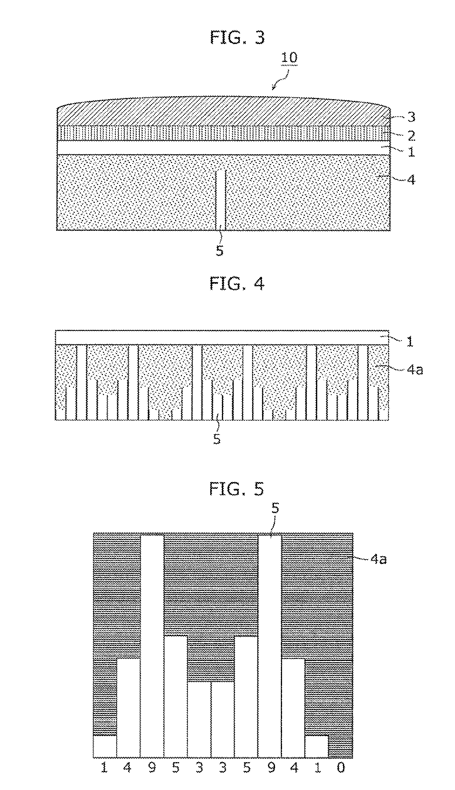
[0064]FIG. 4 is a cross-sectional view of the backing layer 4a according to Embodiment 2 of the present invention. Above the backing layer 4a shown in FIG. 4, in addition to a piezoelectric transducer 1, although not illustrated, a matching layer 2 and an acoustic lens 3 are stacked in the same manner as shown in FIG. 3.
[0065]As shown in FIG. 4, a plurality of acoustic tubes 5 is arranged in the backing layer 4a. Here, the acoustic tubes 5 have lengths (Ln) based on a principle of superposition of acoustic waves. The lengths (Ln) of the acoustic tubes 5 are arranged according to a defined rule.
[0066]Following describes the lengths (Ln) of the acoustic tubes 5.
[0067]FIG. 5 is a cross-sectional view of the backing layer 4 showing an ex...
embodiment 3
[0082]Embodiment 1 and Embodiment 2 have described an example where one or more acoustic tubes are arranged in a backing layer. However, the present invention is not limited to this. It is sufficient that reflectors corresponding to the acoustic tubes are arranged in the backing layer. Embodiment 3 describes the case where the reflectors have properties of the acoustic tubes and serve as acoustic tubes 5.
[0083]FIG. 12A is a cross-sectional view showing an example of a structure of an ultrasonic transducer according to Embodiment 3 of the present invention.
[0084]FIG. 12A shows a specific structure in which an ultrasonic transducer 30 includes the backing layer corresponding to FIG. 10B. The ultrasonic transducer 30 includes a piezoelectric transducer 1 which emits and receives ultrasonic waves, a matching layer 2, an acoustic lens 3, and a backing layer 4c.
[0085]The backing layer 4c is provided in contact with the rear of the piezoelectric transducer 1, and attenuates ultrasonic wav...
PUM
 Abstract
Description
Claims
Application Information
 - R&D Engineer
- R&D Manager
- IP Professional
- Industry Leading Data Capabilities
- Powerful AI technology
- Patent DNA Extraction
Browse by: Latest US Patents, China's latest patents, Technical Efficacy Thesaurus, Application Domain, Technology Topic.
© 2024 PatSnap. All rights reserved.Legal|Privacy policy|Modern Slavery Act Transparency Statement|Sitemap