
Method and a system for estimating a trajectory of a moving body

a technology for moving bodies and trajectory estimation, applied in the field of estimating the trajectory of moving bodies, can solve the problem of not having a hybrid simulation method or system that enables, and achieve the effect of accurate trajectory of moving bodies and low cos

Inactive Publication Date: 2012-05-17
MBDA FRANCE
View PDF6 Cites 12 Cited by
  • Summary
  • Abstract
  • Description
  • Claims
  • Application Information

AI Technical Summary

Benefits of technology

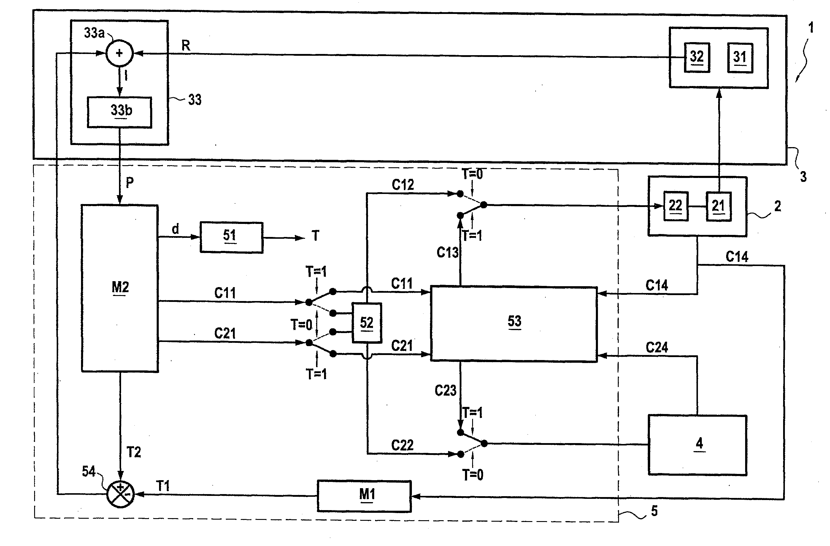
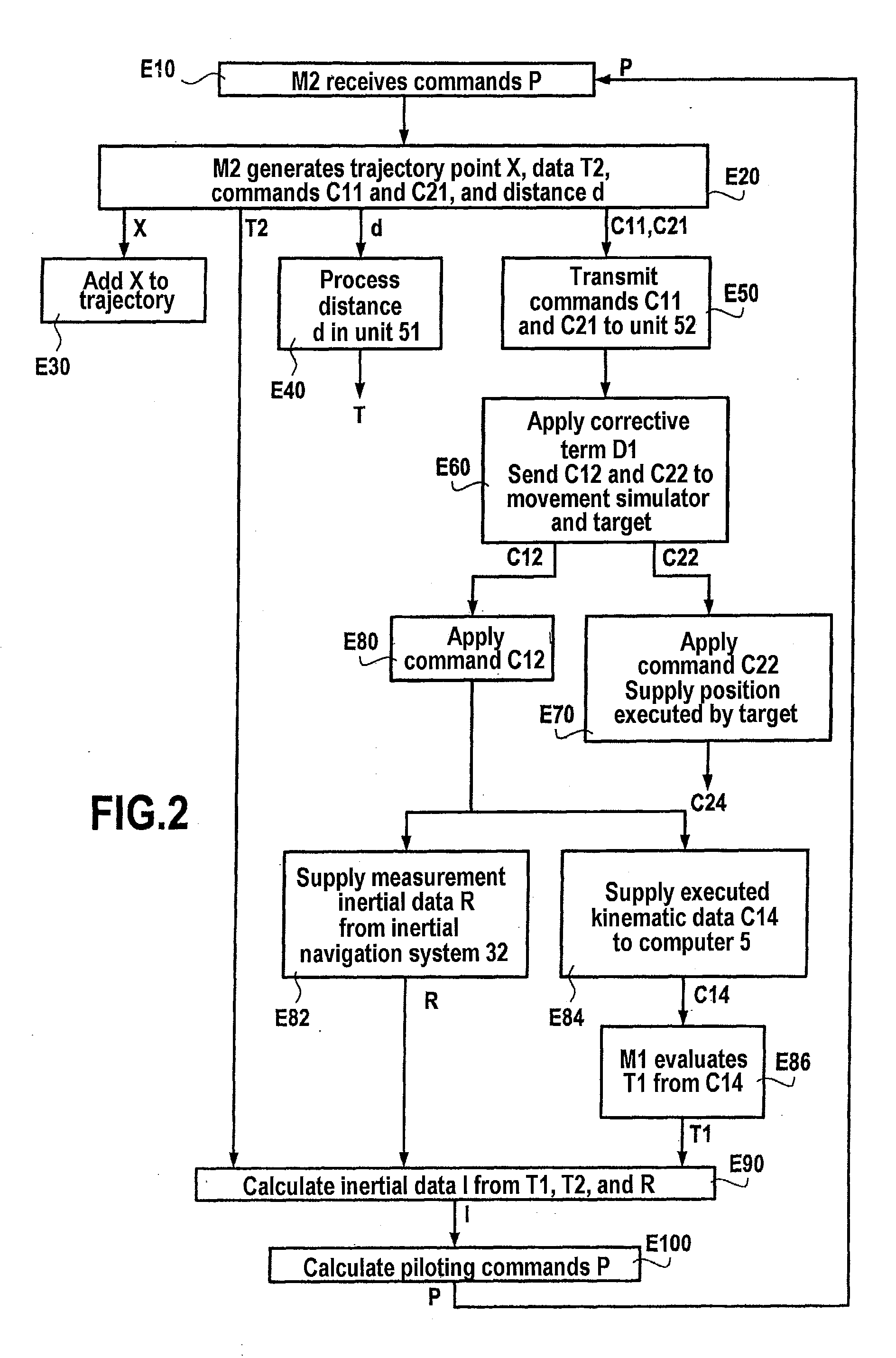
[0031]During a so-called positioning stage, the target and the moving body are positioned relative to predetermined setpoint positions by means of transition kinematics commands substituted for the kinematics commands output by the simulator tool and fed to the movement simulator and to the target. This simplifies positioning the moving body and the target during the positioning stage. This positioning stage ensures that the estimate of the trajectory obtained is an accurate representation of a predefined stage of the attack on the second objective.
[0038]Accordingly, in this particular implementation, compensation is also applied during the attack of the moving body on the first objective. This compensation avoids producing a trajectory to be followed by the moving body in order to reach the first objective that is incompatible with the angular capabilities of the movement simulator and of the target.
[0042]This implementation makes it possible to adapt the setpoint positions for the target and for the movement simulator as a function of the direction of rotation of the moving body, enabling realistic:
[0055]This yields more accurate values for the corrective terms to be applied to the kinematics commands before they are fed to the movement simulator and to the target.
[0064]Thus an underspecified movement simulator may be used for highly dynamic angular transients of the trajectory. This enables an accurate trajectory of the moving body to be obtained at lower cost.

Problems solved by technology

Nevertheless, there is at present no hybrid simulation method or system that enables the trajectory of a moving body to be estimated after detection of an event representative of that moving body overshooting an objective to be reached or of a change of objective requiring to achieve it angular movements exceeding those offered by the means implemented in the hybrid simulation system, notably with a view to making it possible to evaluate the ability of the moving body to re-attack an objective or to change objective during a mission.

Method used


Image

  • Method and a system for estimating a trajectory of a moving body
  • Method and a system for estimating a trajectory of a moving body
  • Method and a system for estimating a trajectory of a moving body

Examples


Embodiment Construction

[0071]As described above, the invention provides a method and a system for estimating a trajectory of a moving body, such as a drone or a missile, in a real navigation environment, for example in order to evaluate its ability to re-attack an objective or to change objective during a mission and attack the new objectives.

[0072]According to the invention, the trajectory of the moving body is computed using a hybrid simulation architecture employing both real subsystems (e.g. the moving body's onboard computer and inertial navigation system, an angular movement simulator, a target representative of an objective to be reached by the moving body) and also digital models of the moving body (e.g. models of its propulsion, fuel consumption, inertial navigation system) and its environment (e.g. models of the atmosphere, terrestrial effects).

[0073]In the present description, this trajectory is made up of different points each defined by a longitude / latitude / altitude triplet evaluated in a ter...


PUM


Abstract

A hybrid simulation method uses a simulator tool feeding kinematics commands to a movement simulator on which a moving body is mounted and to a target representative of an objective to be reached by the moving body, and on detection of an event representative of overshooting or changing a first designated objective for this moving body, the method includes a positioning stage associated with a second designated objective for the moving body, including comparing positions executed by the movement simulator in response to transition kinematics commands with a first predetermined setpoint position and activating a first marker if a position substantially the same as the first setpoint position is detected; comparing positions executed by the target in response to transition kinematics commands with a second predetermined setpoint position and activating a second marker if a position substantially the same as the second setpoint position is detected; when the first and second markers are activated, a step of evaluating a difference between the current kinematics command supplied to the movement simulator and the target by the digital simulator tool; and, if this difference is below a particular threshold, a piloting stage including applying corrective terms linked to the setpoint positions to the kinematics commands coming from the simulator tool before they are fed to the movement simulator and to the target.

Description

BACKGROUND OF THE INVENTION[0001]The field of the present invention is validating the operational capabilities of a moving or airborne body, for example a drone, a missile, etc.[0002]The invention relates more particularly to estimating the trajectory of a moving body in a real navigation environment, notably after detecting an overshoot of a designated objective for the moving body or a change of objective. Here objective means a target or destination that the moving body is to reach, designated in the form of geographical coordinates, for example.[0003]In the meaning of the invention, references to a moving body “overshooting” an objective mean that the moving body has not reached the objective (for example it has missed the objective). Similarly, the remainder of the description refers to a moving body “attacking” an objective while it is attempting to reach the objective.[0004]Thus, although this is not limiting on the invention, the invention preferably enables evaluation of th...

Claims


Application Information

Patent Timeline
Patent Type & Authority Applications(United States)
IPC IPC(8): G05D1/12
CPCG05D1/12F42B15/01
Inventor BOURZIER, LAURENT
Owner MBDA FRANCE
Learn More