Composite Centrifugal Compressor Wheel

a compressor wheel and compressor technology, applied in the field of centrifugal compressor wheels, can solve the problems of limiting the operating life of the turbocharger, limiting the operational life of the wheels and turbochargers that incorporate, and relatively high radial tensile loading

Active Publication Date: 2012-05-24
GM GLOBAL TECH OPERATIONS LLC
View PDF5 Cites 38 Cited by
  • Summary
  • Abstract
  • Description
  • Claims
  • Application Information

AI Technical Summary

Problems solved by technology

While effective, cast centrifugal compressor wheels of this type are subject to metal fatigue that limits the operating lifetime of the turbocharger.
This leads to relatively high radial tensile loading; particularly in the hub portion of the wheel which must support the radial wheel mass.
As the hub is cyclically stressed, inclusions, voids and other defects associated with the casting process

Method used


Image

  • Composite Centrifugal Compressor Wheel
  • Composite Centrifugal Compressor Wheel
  • Composite Centrifugal Compressor Wheel

Examples


Embodiment Construction

[0013]The following description is merely exemplary in nature and is not intended to limit the present disclosure, its application or uses. It should be understood that throughout the drawings, corresponding reference numerals indicate like or corresponding parts and features.

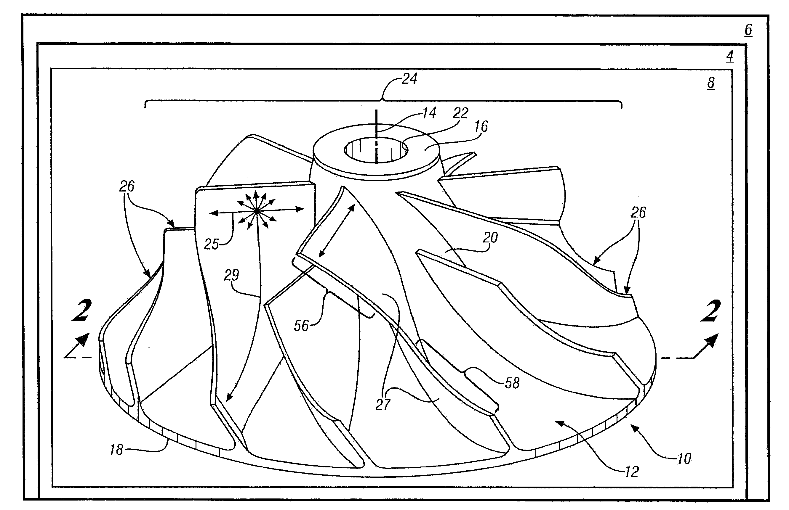
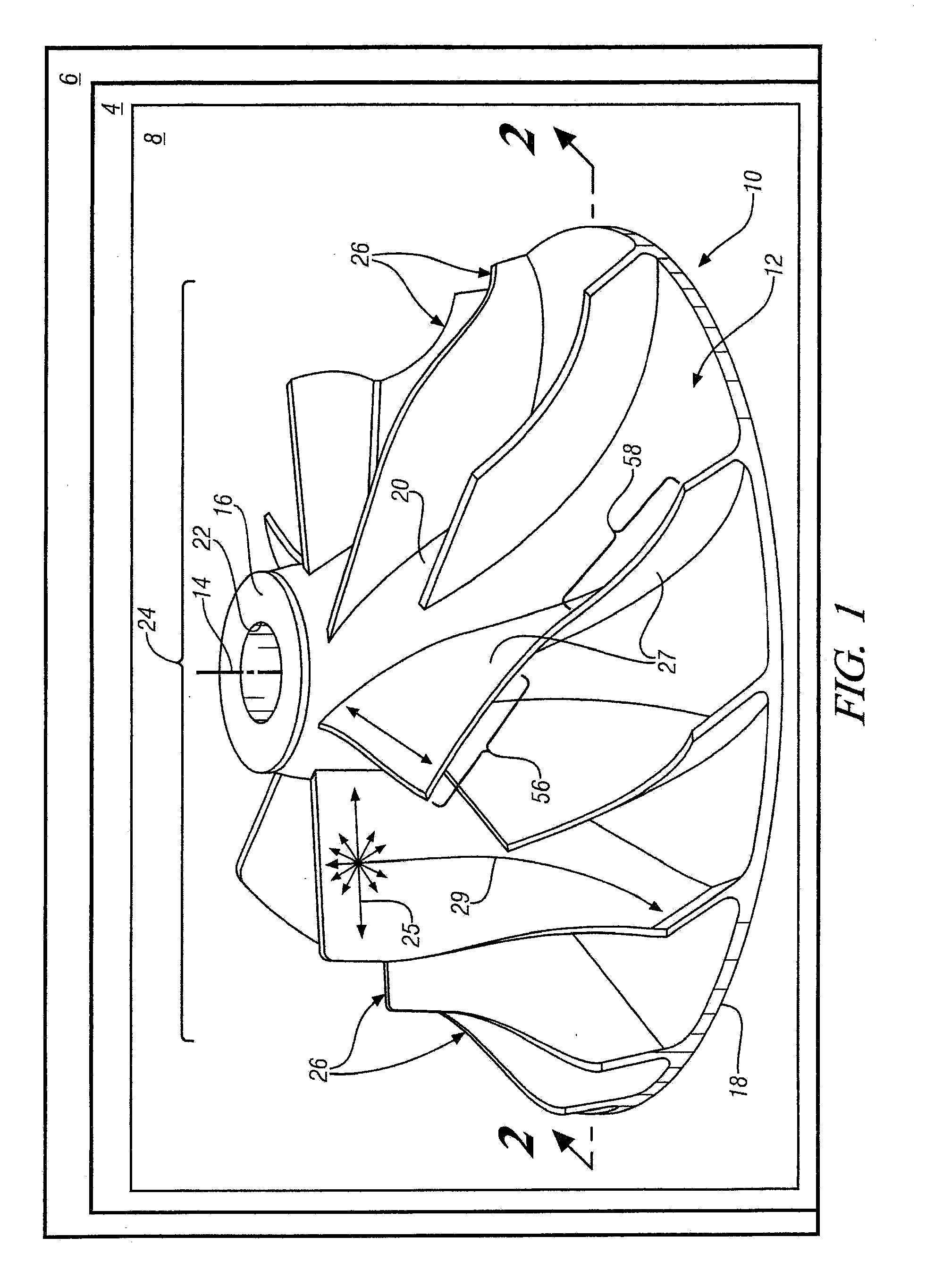
[0014]In accordance with exemplary embodiments of the present invention, as illustrated in FIGS. 1-4, a centrifugal centrifugal compressor wheel 10 for use as a centrifugal impeller in a rotatable compressor 8 is disclosed. Centrifugal compressor wheel 10 is suitable for use as a centrifugal impeller in many rotatable compressor 8 applications, including compressors 8 for various exhaust driven turbochargers 4 or the like, for internal combustion engines 6.

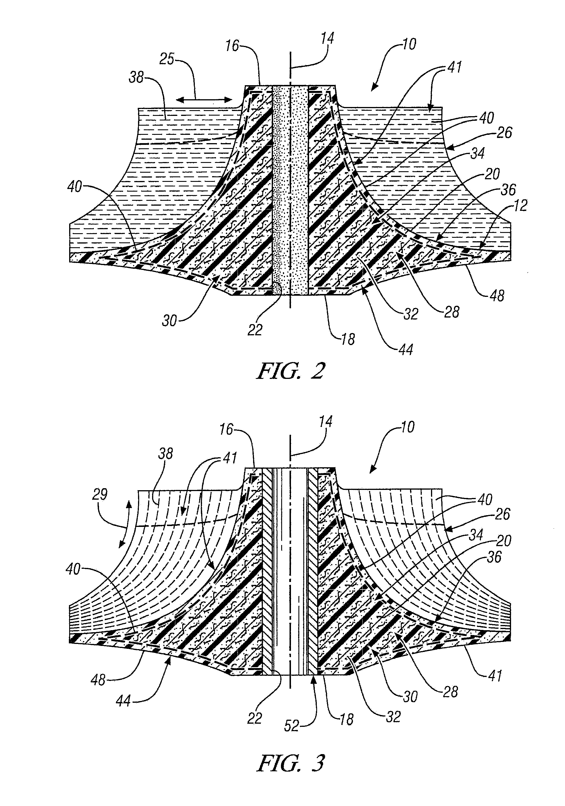
[0015]Centrifugal compressor wheel 10 includes an axially extending hub 12 that extends along a longitudinal axis 14. Axially extending hub 12 has an inlet end 16, an outlet end 18, an arcuate outer surface 20 and a shaft bore 22 and is configured for detacha...


PUM


Abstract

A centrifugal compressor wheel for a turbocharger is disclosed. The wheel includes an axially extending hub having an inlet end, an outlet end, an arcuate outer surface and a shaft bore. The wheel also includes a blade array disposed on the outer surface of the hub, the blade array comprising a plurality of circumferentially-spaced, radially and axially extending, arcuate centrifugal impeller blades disposed thereon; the hub and the blade array comprising a non-woven, discontinuous-fiber-filled, polymer matrix composite material.

Description

FIELD OF THE INVENTION[0001]Exemplary embodiments of the present invention are related to a centrifugal compressor wheel for use in a compressor, and more particularly to a composite centrifugal compressor wheel for use in a compressor of a turbocharger.BACKGROUND[0002]Centrifugal compressors are used in turbochargers, superchargers, and the like. They comprise a centrifugal compressor wheel that includes an array of aerodynamically contoured impeller blades supported by a central hub section. The hub is mounted on a rotatable driven shaft that is driven, in the case of a turbocharger, by the turbine wheel. For turbochargers, the hub section generally includes a central axial bore into which the shaft extends and is fastened to the hub. Fastening can take any suitable form, such as the use of a threaded shaft and hub, a keyed hub or, alternately, a nose of the shaft may extend through the hub and be fastened thereto using a nut to tighten the hub against a shoulder or other diametri...

Claims


Application Information

Patent Timeline
IPC IPC(8): F01D5/28F02C6/12
CPCF04D29/023F04D29/30F04D29/284F05D2300/43F05D2300/603
Inventor HOMMES, DANIEL J.WILLIAMS, CARNELL E.
Owner GM GLOBAL TECH OPERATIONS LLC
Why Eureka
Try Eureka