Premix air heater

a technology of air heater and pre-mixing, which is applied in the direction of air heater, fluid heater, lighting and heating apparatus, etc., can solve the problems of over-pressurization of combustion fan in combustion chamber and heat exchanger

Inactive Publication Date: 2012-05-24
REZNOR
View PDF7 Cites 8 Cited by
  • Summary
  • Abstract
  • Description
  • Claims
  • Application Information

AI Technical Summary

Problems solved by technology

One drawback with using such conventional premix heaters is that the combustio

Method used


Image

  • Premix air heater
  • Premix air heater
  • Premix air heater

Examples


Embodiment Construction

[0009]The following detailed description refers to the accompanying drawings. The same reference numbers in different drawings may identify the same or similar elements. Also, the following detailed description does not limit the invention.

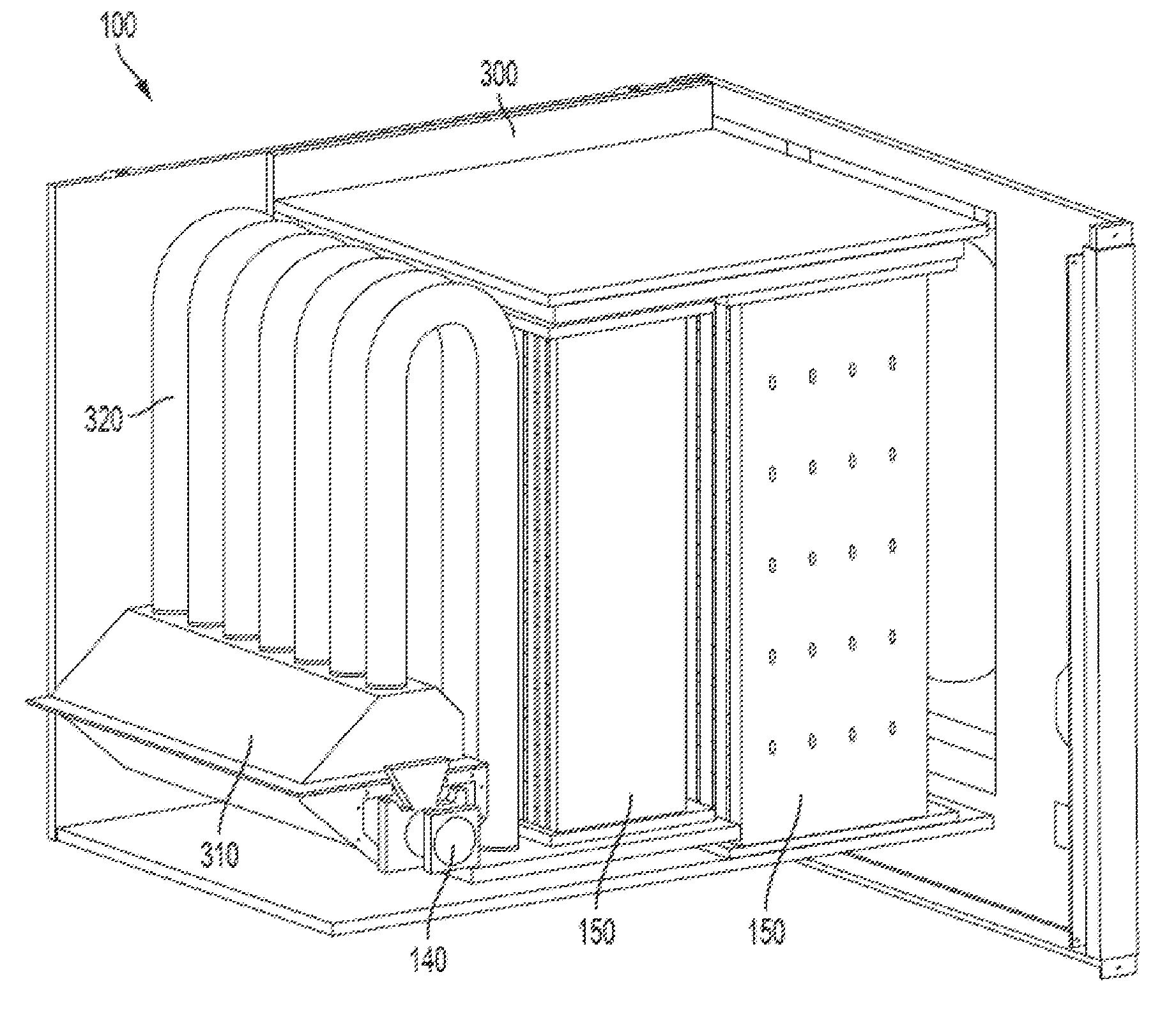
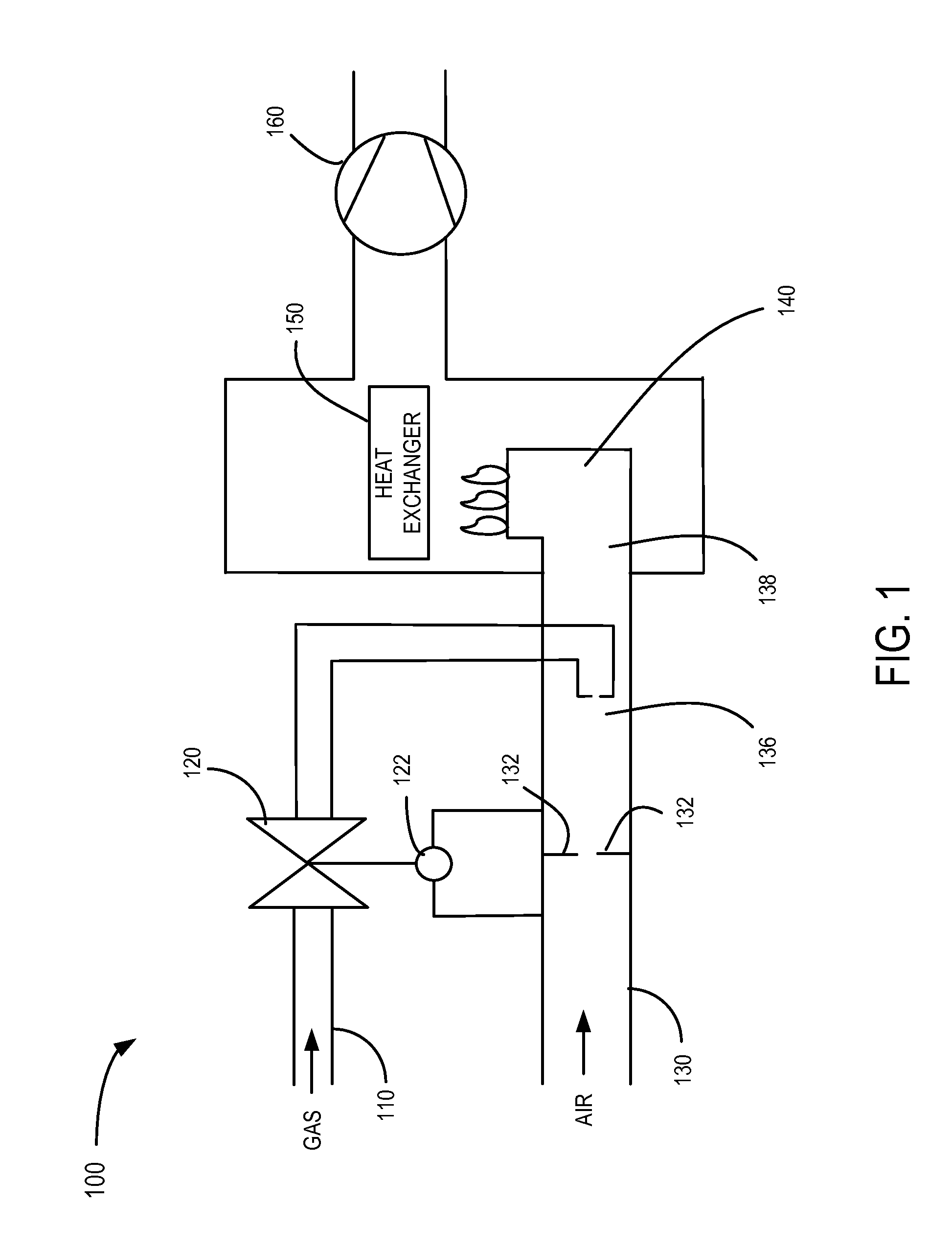
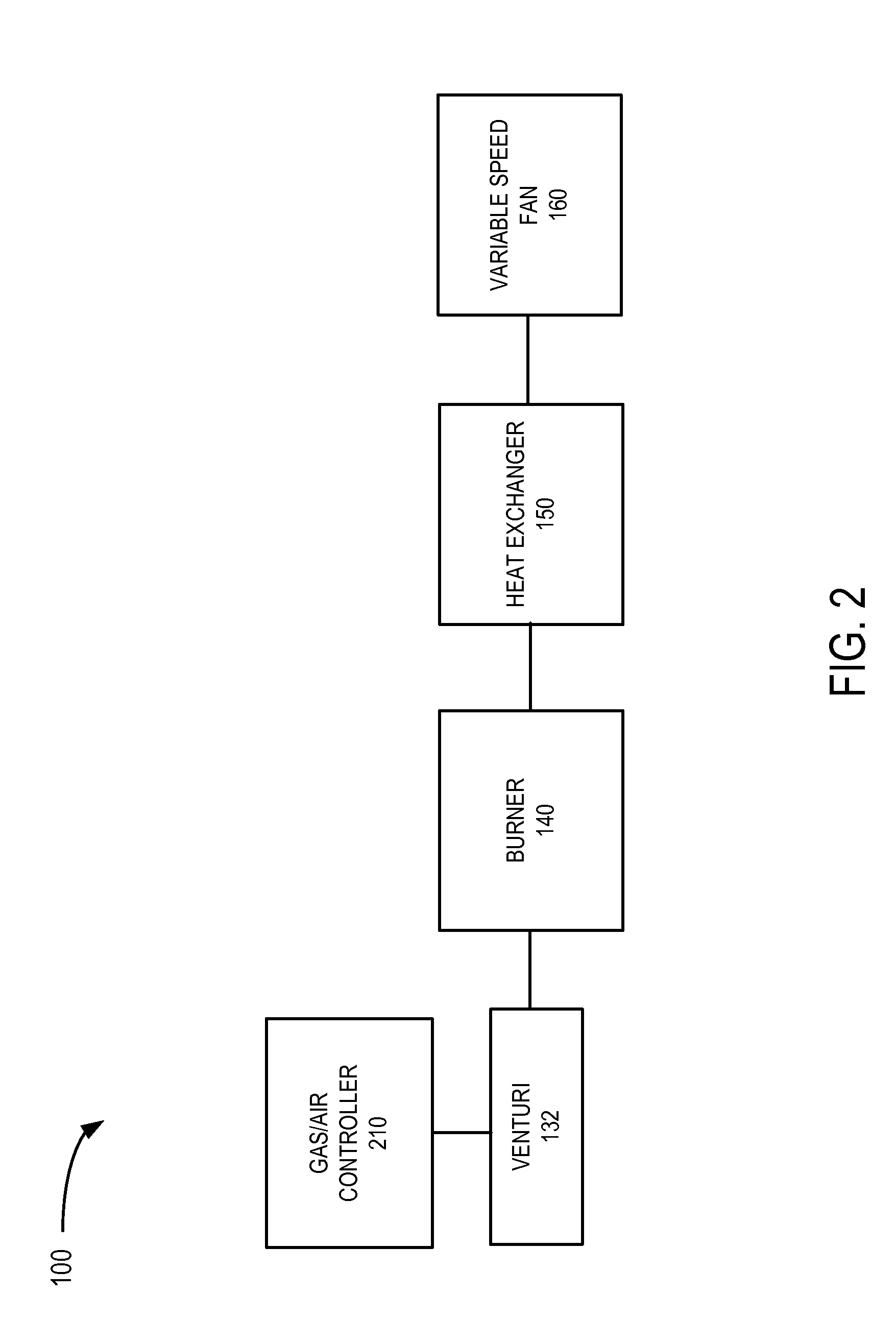
[0010]Embodiments described herein provide a premix air heater that includes a downstream fan that pulls or draws air through a heat exchanger. As a result of the location of the fan, the heat exchanger is effectively under a negative pressure, which helps prevent introduction of flue gases into an interior space. For example, a small leak in the combustion chamber or heat exchanger will not result in flue gases being expelled into the interior space. The fan may also be a variable speed fan that does not affect the gas-air mixture provided to the combustion chamber, which allows the air heater to achieve high efficiency at all loads.

[0011]FIG. 1 is a schematic view of a premix heater unit 100 in accordance with an exemplary implementation. Referr...


PUM


Abstract

A gas-fired heater includes a gas supply line, an air supply line, a valve coupled to the gas supply line and a controller coupled to the valve. The controller is configured to control the valve to control a gas-air mixture. The gas-fired heater also includes a burner configured to receive the gas-air mixture and burn the gas-air mixture, and a heat exchanger coupled to the burner. The heat exchanger is configured to perform a heat exchange process and output heated air. The gas-fired heater further includes a combustion fan located downstream of the heat exchanger, the combustion fan being configured to pull or draw flue gases through the heat exchanger.

Description

RELATED APPLICATION[0001]This application claims priority under 35 U.S.C. §119 based on U.S. Provisional Patent Application No. 61 / 414,997, filed Nov. 18, 2010, the disclosure of which is hereby incorporated herein by reference.BACKGROUND INFORMATION[0002]Conventional premix gas fired air heaters typically use a combustion fan to push a gas / air mixture through a heat exchanger. This is accomplished by means of a combustion fan located upstream of the heat exchanger, which pushes the gas / air mixture towards the combustion chamber. One drawback with using such conventional premix heaters is that the combustion chamber and heat exchanger are often over-pressurized by the combustion fan.BRIEF DESCRIPTION OF THE DRAWINGS[0003]FIG. 1 is a schematic diagram of a premix heater consistent with an exemplary implementation;[0004]FIG. 2 is a simplified functional block diagram of the premix heater of FIG. 1;[0005]FIGS. 3A and 3B are isometric views of an exemplary premix heater consistent with ...

Claims


Application Information

Patent Timeline
IPC IPC(8): F24H3/02
CPCF23N1/022F23N3/082F23N5/184F23N2005/182F23N2033/04Y02B30/102F28D21/0008F24H3/087F24H3/105F24H8/00F23N2033/10F23N2233/04F23N2233/10F23N2900/05181Y02B30/00
Inventor GRAMMENS, CHRISRAES, NIKO
Owner REZNOR
Why Eureka
Try Eureka