Device for measuring current

a current measurement and current technology, applied in the direction of measurement devices, substation equipment, instruments, etc., can solve the problems of reducing testing efficiency, connectors falling off, complicated and trivial steps involved in such a current testing procedure, etc., to achieve accurate test results, simple and convenient steps, and efficient overall yield of portable electronic devices

Inactive Publication Date: 2012-05-24
ASKEY COMP
View PDF4 Cites 3 Cited by
  • Summary
  • Abstract
  • Description
  • Claims
  • Application Information

AI Technical Summary

Benefits of technology

[0006]Another objective of the present invention is to provide a device for measuring current that allows the testing personnel to obtain a more accurate test result.
[0011]Therefore, the present invention allows the testing personnel to perform a current measuring procedure on the portable electronic apparatus through simple and convenient steps, which eliminates the shortcoming of the prior art in which a significant amount of manual work is required. Thus, a more accurate test result can be obtained. Further, the overall yield of the portable electronic apparatus is efficiently improved, thus reducing the production cost of the manufacturer is reduced.

Problems solved by technology

However, steps involved in such a current testing procedure are complicated and trivial.
There is a concern that the connectors might fall off during the test.
In addition, manual testing and determination are required, thus reducing testing efficiency.

Method used


Image

  • Device for measuring current
  • Device for measuring current

Examples


Embodiment Construction

[0015]The present invention is described by the following specific embodiments. Those with ordinary skills in the arts can readily understand the other advantages and functions of the present invention after reading the disclosure of this specification. The present invention can also be implemented with different embodiments. Various details described in this specification can be modified based on different viewpoints and applications without departing from the scope of the present invention.

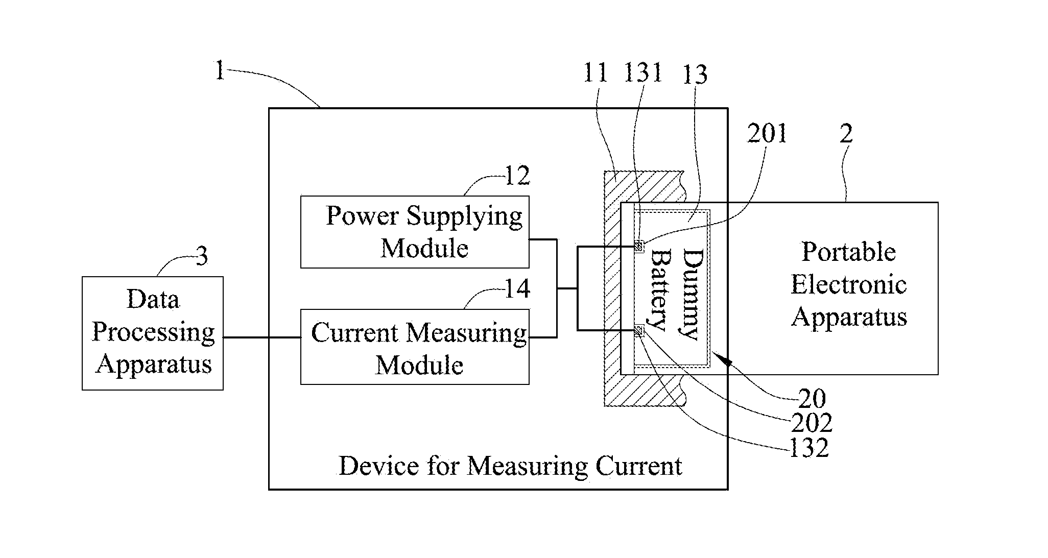
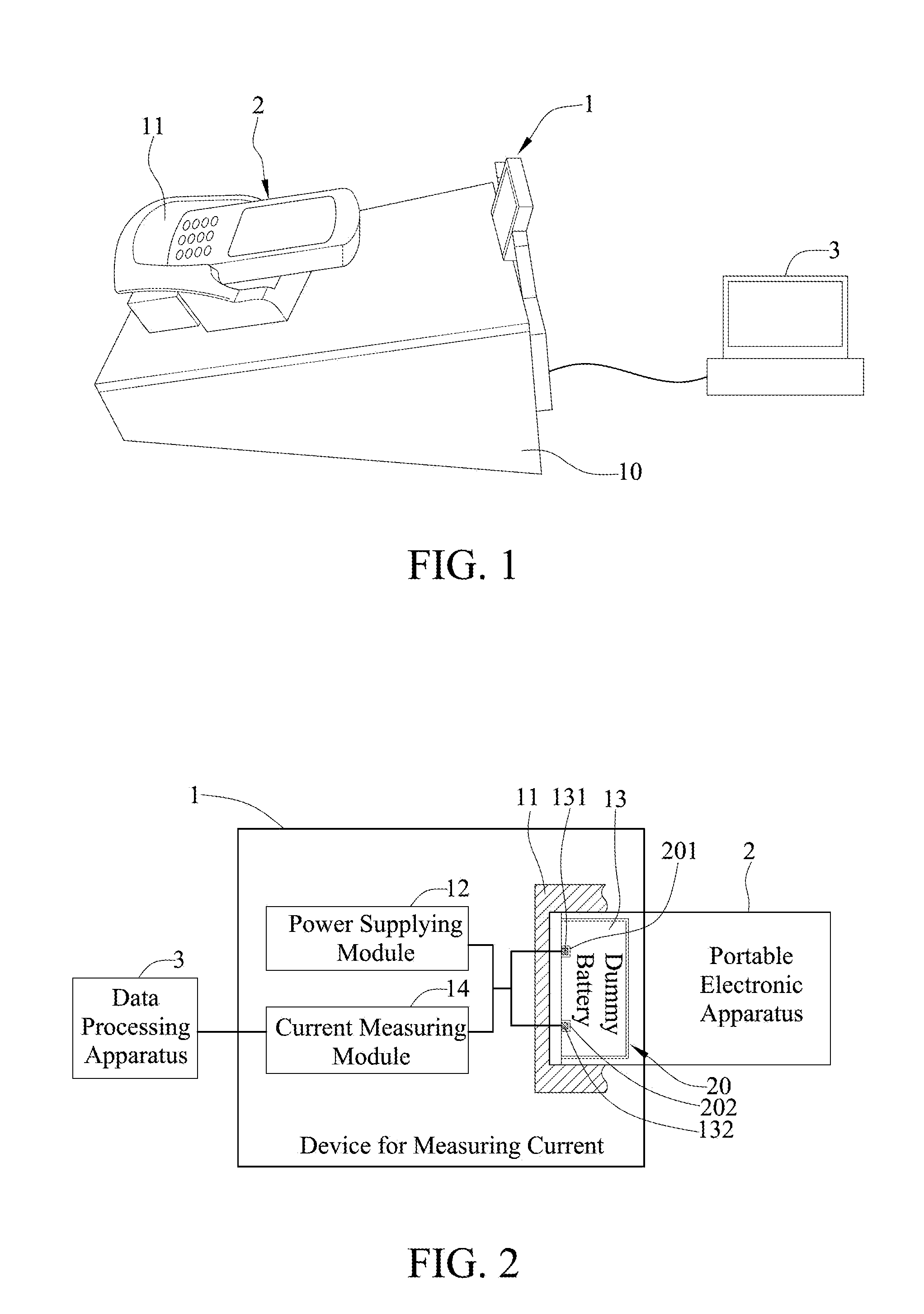
[0016]Referring to FIGS. 1 and 2 together, a schematic diagram depicting the appearance of a device for measuring current according to an embodiment of the present invention is shown in FIG. 1, and a block diagram depicting basic functional architecture of the device for measuring current according to an embodiment of the present invention is shown in FIG. 2. As shown, the device for measuring current 1 includes a body 10, a container 11, a power supplying module 12, a dummy battery 13, and a cu...


PUM


Abstract

A device for measuring current is connected to a data processing apparatus loaded with a current value comparison program for performing a quality test on a portable electronic apparatus with a battery. The portable electronic apparatus has a battery compartment for receiving the battery. The device for measuring current includes: a power supplying module for generating a low-voltage current; a dummy battery with a shape of the battery for inserting into the battery compartment, the dummy battery electrically connected to the power supplying module and the portable electronic apparatus to provide the low-voltage current generated by the power supply module to the portable electronic apparatus, forming a power supply loop to the portable electronic apparatus; and a current measuring module electrically connected to the power supply loop for measuring a current value of the power supply loop when the portable electronic apparatus is performing a specific function and transmitting the measured current value to the data processing apparatus for comparison. The present invention does not heavily rely on manual operations to measure the current of the portable electronic apparatus.

Description

FIELD OF THE INVENTION[0001]The present invention relates to devices for measuring current, and more particularly, to a device for measuring current of a portable electronic apparatus with a built-in battery.BACKGROUND OF THE INVENTION[0002]Generally, manufacturers of electronic devices perform a series of tests on their products before shipping or mass production in order to provide consumers with good-quality products. Among them, one of the tests determines whether current consumptions of a portable electronic apparatus (e.g. a palm computer or smart phone) under different operating conditions are all within their ideal ranges, so as to detect any faulty products at an earlier stage.[0003]Specifically, testing personnel connects a portable electronic apparatus to be tested to an external power supply, and connects a digital multimeter to the power supply. Then, the power supply is operated to provide a low voltage to the portable electronic apparatus, and the portable electronic ...

Claims


Application Information

Patent Timeline
Patent Type & Authority Applications(United States)
IPC IPC(8): G01R19/00
CPCG01R19/0092H04M1/24
Inventor LIU, CHUN-GUOHSIEH, CHING-FENG
Owner ASKEY COMP
Why Eureka
Try Eureka