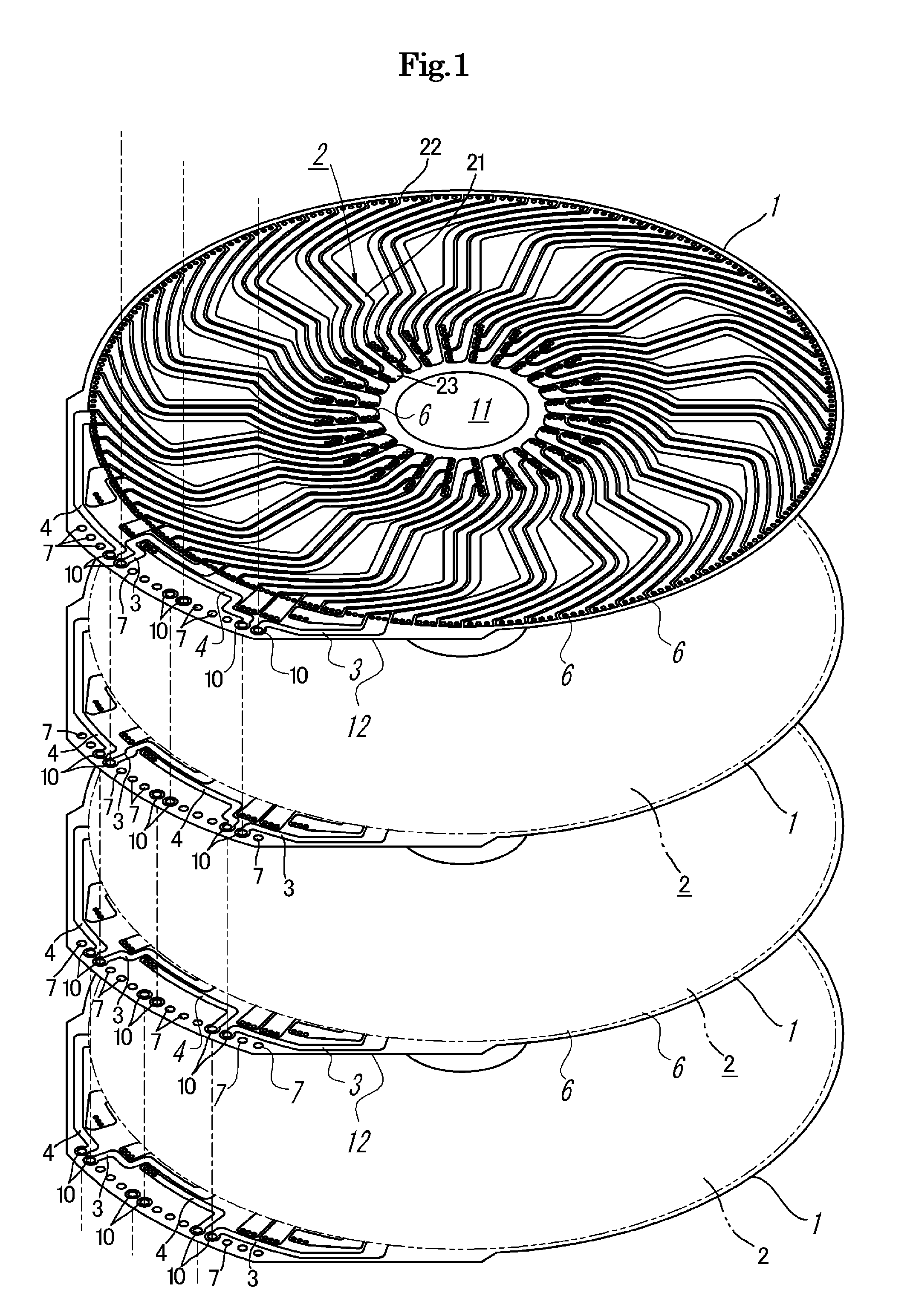
[0014]According to the coil apparatus of the present invention, the disc-type coils having the same conductor patterns are laminated while fitting magnetic pole positions by just changing the arrangement of the leading pattern and the terminating pattern of each disc-type coil to be laminated, and hence a phase of the conductor patterns in each disc-type coil itself is no longer necessary. That is, to fit positions of
magnetic poles of each disc-type coil, the insulating substrate does not have to be rotated, and just laminating these discs as they are can suffice, whereby the lamination work of the disc-type coils can be facilitated and a manufacturing cost can be reduced. Further, since at least the n+1 holes configured to form the lamination through holes are provided with respect to the n discs to be laminated in accordance with each circuit of each disc-type coil, various
electrical connection patterns between the disc-type coils can be readily obtained by laminating the disc-type coils at the same position and arbitrary selecting positions of the holes where the terminating pattern is connected to the leading pattern without rotating the disc-type coils having the same conductor pattern, i.e., the disc-type coils of one type to provide a phases. For example, series connection can be obtained by a simple lamination structure that the lamination through holes are sequentially connected while displacing hole positions one by one in accordance with each disc-type coil.
[0015]Furthermore, since the conductor patterns of each disc-type coil that is laminated via the lamination through holes connected to the leading pattern and the terminating pattern, the conductor patterns of each disc-type coil to be laminated can have a degree of freedom in connection. That is, an
electrical connection relationship between the disc-type coils to be laminated can be freely changed by just changing positions of lamination holes, i.e., positions of the lamination through holes connected to the leading pattern and the terminating pattern. For example, it is possible to achieve connection that the plurality of disc-type coils to be laminated are connected in series or connected in parallel or they are connected both in parallel and in series. As a result, a value of a current flowing through the coils can be increased, a
voltage can be raised, or a large current can be assured while securing a
high voltage. Therefore, a high-capacity output, which cannot be realized in a conventional disc-type coil apparatus, can be readily attained.
[0016]Furthermore, since the same disc-type coils, in which positions of the conductor patterns formed on the insulating substrate and holes configured to form the lamination through holes are equal, can be combined to be used based on the connection that these disc-type coils are connected in series or in parallel or they are connected both in series and in parallel, induction devices having different outputs can be fabricated by changing the number of the coils to be combined, and a cost can be reduced by using the same components (the disc-type coils).
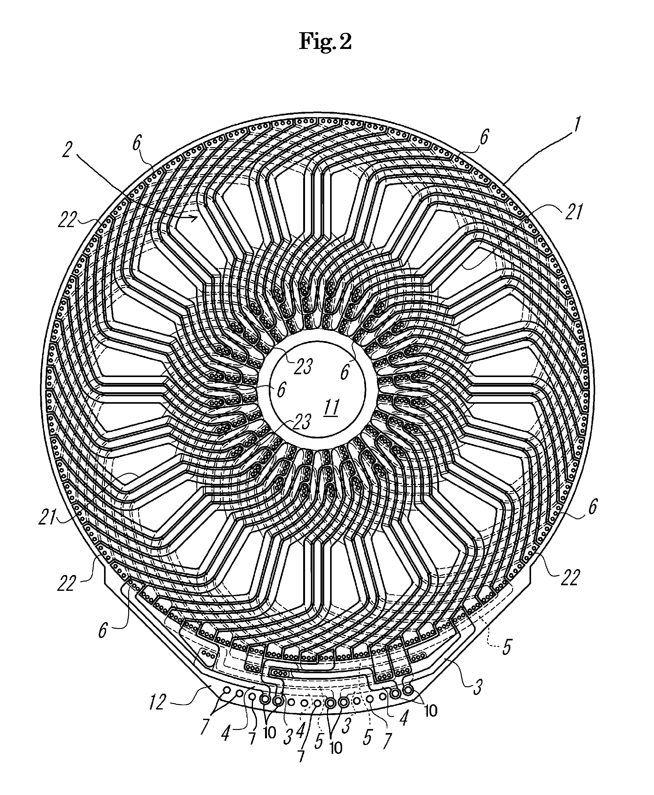
[0017]Moreover, in the coil apparatus according to the present invention, when the holes configured to form the lamination through holes are congregated in proximity to each other, the leading pattern, the terminating pattern, and the connection pattern of each disc-type coil are aggregated, thereby reducing a size of the coil apparatus.
[0018]Additionally, in the coil apparatus according to the present invention, when the holes configured to form the lamination through holes are arranged in the
flange portion protruding toward the outside from the outer circumference of the insulating substrate or in the space on the inner circumferential side of the conductor pattern on the insulating substrate, since the leading pattern, the terminating pattern, and the connecting pattern are drawn to the outer side of the conductor pattern, these patterns can be easily and assuredly connected to the conductor pattern, and the conductor pattern itself can be highly densely formed. Therefore, the high-output coil apparatus can be manufactured at a low cost.
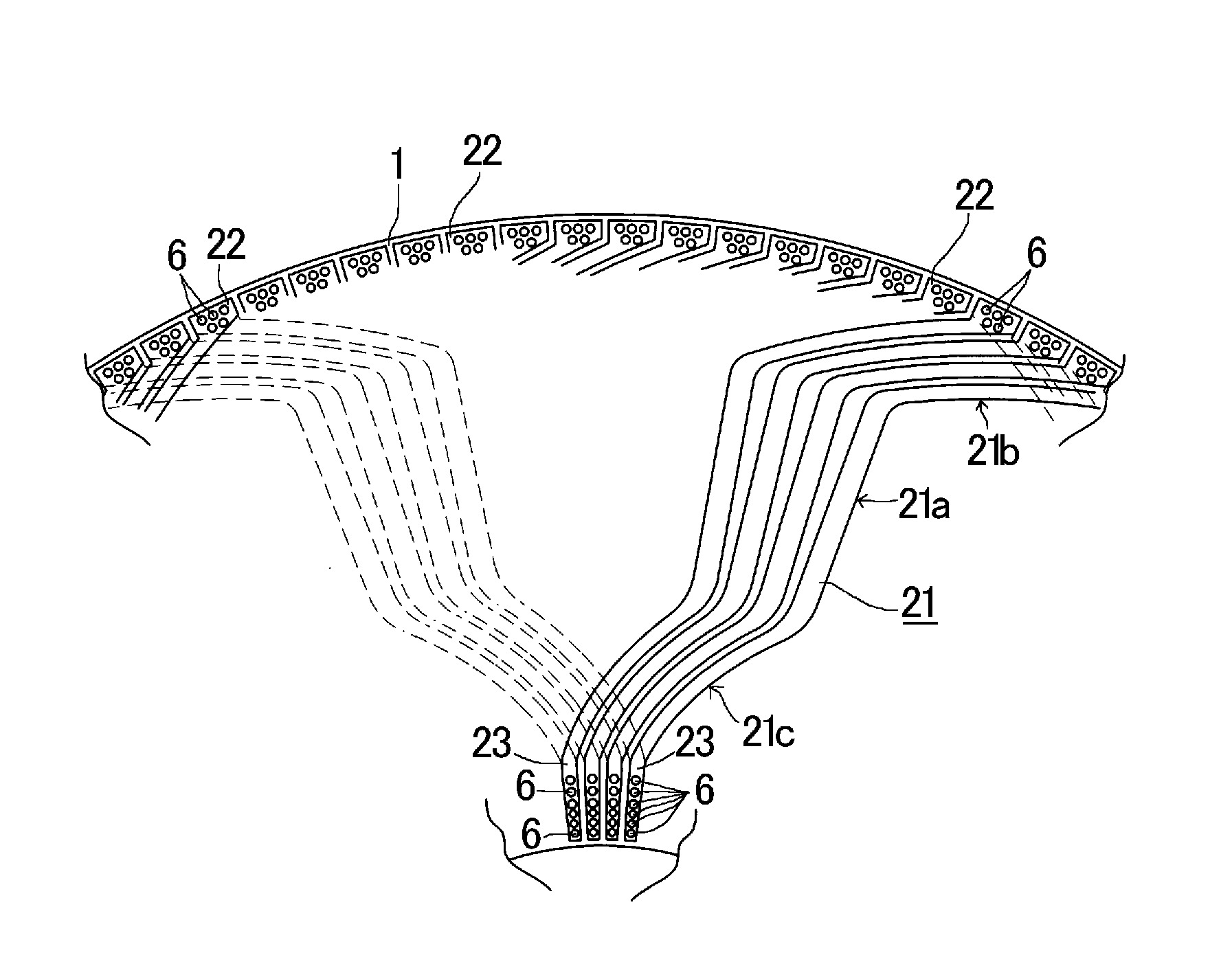
[0019]Further, according to the conductor pattern folded back in a
wave shape alternately between the front surface and the back surface of the insulating substrate to constitute one coil, the series connection or the parallel connection of the plurality of coils can be facilitated by utilizing the positions of the through hole connections, thereby changing a current or a
voltage flowed through each coil without changing the conductor pattern. In particular, in cases where each through hole land on the inner circumferential side has an area expanded in the radial direction of the insulating substrate, an extended line of an outline of the through hole land on the inner circumferential side in the radial direction has a
wedge shape that coincides with the center of the insulating substrate, each of the conductor is drawn from an outer end portion of the through hole land on the inner circumferential side in the radial direction, and a plurality of through holes configured to connect the conductor pattern on the front surface with the conductor pattern on the back surface are formed in the radial direction of the insulating substrate, an
electrical conduction area of the through hole connections in one through hole land on the inner circumferential side can be expanded without circumferentially expanding each through hole land on the inner circumferential side, and a value of a current flowing in the through hole connections in the entire through hole lands on the inner circumferential side can be increased even though a through hole plating thickness is unchanged. Furthermore, when wiring is installed so as to draw each conductor from an outer end portion of each through hole land on the inner circumferential side in the radial direction, a width of the conductor near the through hole land on the inner circumferential side is equal to that of the through hole land on the inner circumferential side, and a value of the current flowing through the entire conductor pattern is no longer restricted by the conductor width. Moreover, in cases where the through hole lands on the inner circumferential side of the plurality of conductors constituting the same magnetic pole of the same circuit are arranged to be aligned on a plurality of different concentric circles in the radial direction of the insulating substrate and a plurality of through holes configured to connect the conductor pattern on the front surface with the conductor pattern on the back surface are formed, the
electrical conduction area of the through hole connections in the through hole lands can be expanded, and a value of the current flowing in the through hole connections in the entire through hole lands can be increased and electrical resistance in the through hole connections can be reduced even though the through hole plating thickness is unchanged.

