Radio Frequency Identification (RFID) Connected Tag Communications Protocol And Related Systems And Methods
a technology of connected tags and communication protocols, applied in the field of radio frequency (rf) communications, can solve problems such as life-threatening interruption of power, information being exchanged improperly from one party, and affecting the ability of the connected tag to communicate with the connected tag, and achieve the effect of reducing the amount of time it takes to determine the connectivity between the rfid tag and the associated system
- Summary
- Abstract
- Description
- Claims
- Application Information
AI Technical Summary
Benefits of technology
Problems solved by technology
Method used
Image

Examples
Embodiment Construction
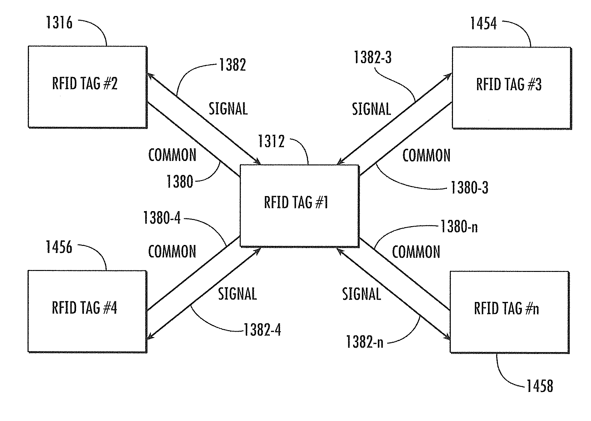
[0009]Embodiments disclosed in the detailed description include physical and logical protocols, and related systems and methods, for two or more radio frequency (RF) identification (RFID) tags to communicate with each other. One or more RFID tags may communicate with one or more other RFID tags. Communications can include using direct electrical connections in addition to standard propagated or reflected field communication via their antennas. By communicating using direct electrical connections between the RFID tags, the amount of time it takes to determine connectivity between RFID tags is reduced as a result of not having to perform a significant number of unique queries between the RFID tags and an RFID reader, each of which may involve many commands and responses between the RFID reader and the set of RFID tags.
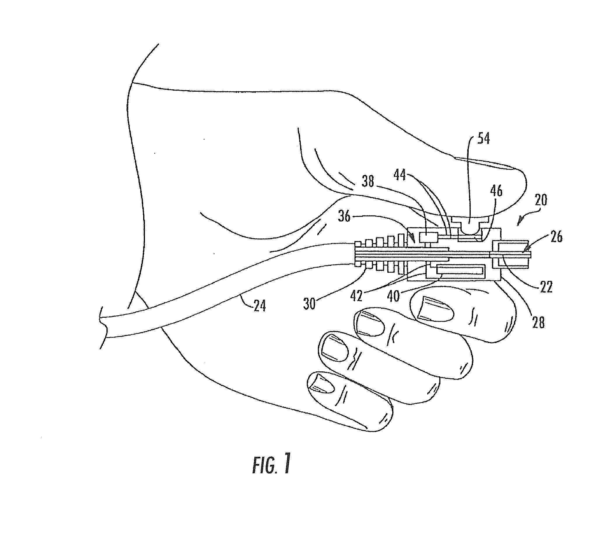
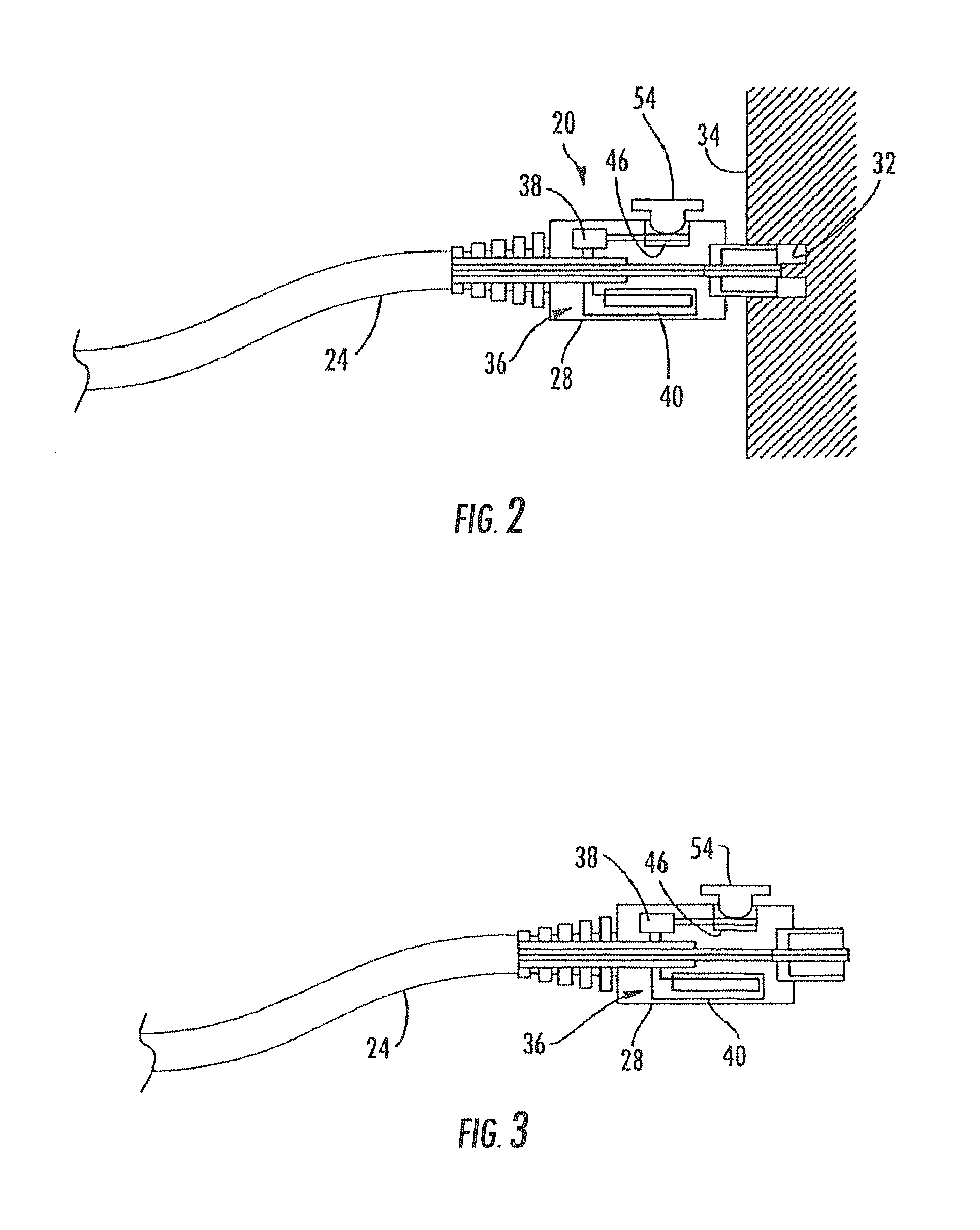
[0010]In one embodiment, a system is disclosed that includes a first RFID tag and a second RFID tag, wherein the first and second RFID tags are configured to mate to eac...
PUM
 Abstract
Description
Claims
Application Information
 - R&D Engineer
- R&D Manager
- IP Professional
- Industry Leading Data Capabilities
- Powerful AI technology
- Patent DNA Extraction
Browse by: Latest US Patents, China's latest patents, Technical Efficacy Thesaurus, Application Domain, Technology Topic.
© 2024 PatSnap. All rights reserved.Legal|Privacy policy|Modern Slavery Act Transparency Statement|Sitemap