Variable directivity antenna apparatus including parasitic elements having cut portion of rectangular shape

a technology of antenna apparatus and parasitic elements, which is applied in the direction of electrical apparatus, simultaneous aerial operations, antennas, etc., can solve the problems of fading mainly caused by equipment, and achieve the effect of increasing the antenna gain and the fb ratio

Active Publication Date: 2012-05-24
PANASONIC CORP
View PDF10 Cites 6 Cited by
  • Summary
  • Abstract
  • Description
  • Claims
  • Application Information

AI Technical Summary

Benefits of technology

[0016]According to the variable directivity antenna apparatus of the present invention, a cut portion having a rectangular shape is formed at a corner portion of another end of the parasitic element. Therefore, it is possible to provide a dual-band variable directivity antenna apparatus capable of securing a relatively higher antenna gain than that of the prior art, and securing a relatively larger FB ratio than that the prior art throughout a wide range at the higher frequency band.

Problems solved by technology

In addition, when wireless communication apparatuses that are mounted in portable equipments such as a small-sized television broadcasting receiver apparatus such as a one-segment television broadcasting receiver apparatus, a portable DVD player or the like, and a wireless access point communicate with each other, the fading is mainly caused when the equipments are moved.

Method used


Image

  • Variable directivity antenna apparatus including parasitic elements having cut portion of rectangular shape
  • Variable directivity antenna apparatus including parasitic elements having cut portion of rectangular shape
  • Variable directivity antenna apparatus including parasitic elements having cut portion of rectangular shape

Examples


Embodiment Construction

[0054]Preferred embodiments according to the present invention will be described below with reference to the attached drawings. In the following preferred embodiments, components similar to each other are denoted by the same reference numerals.

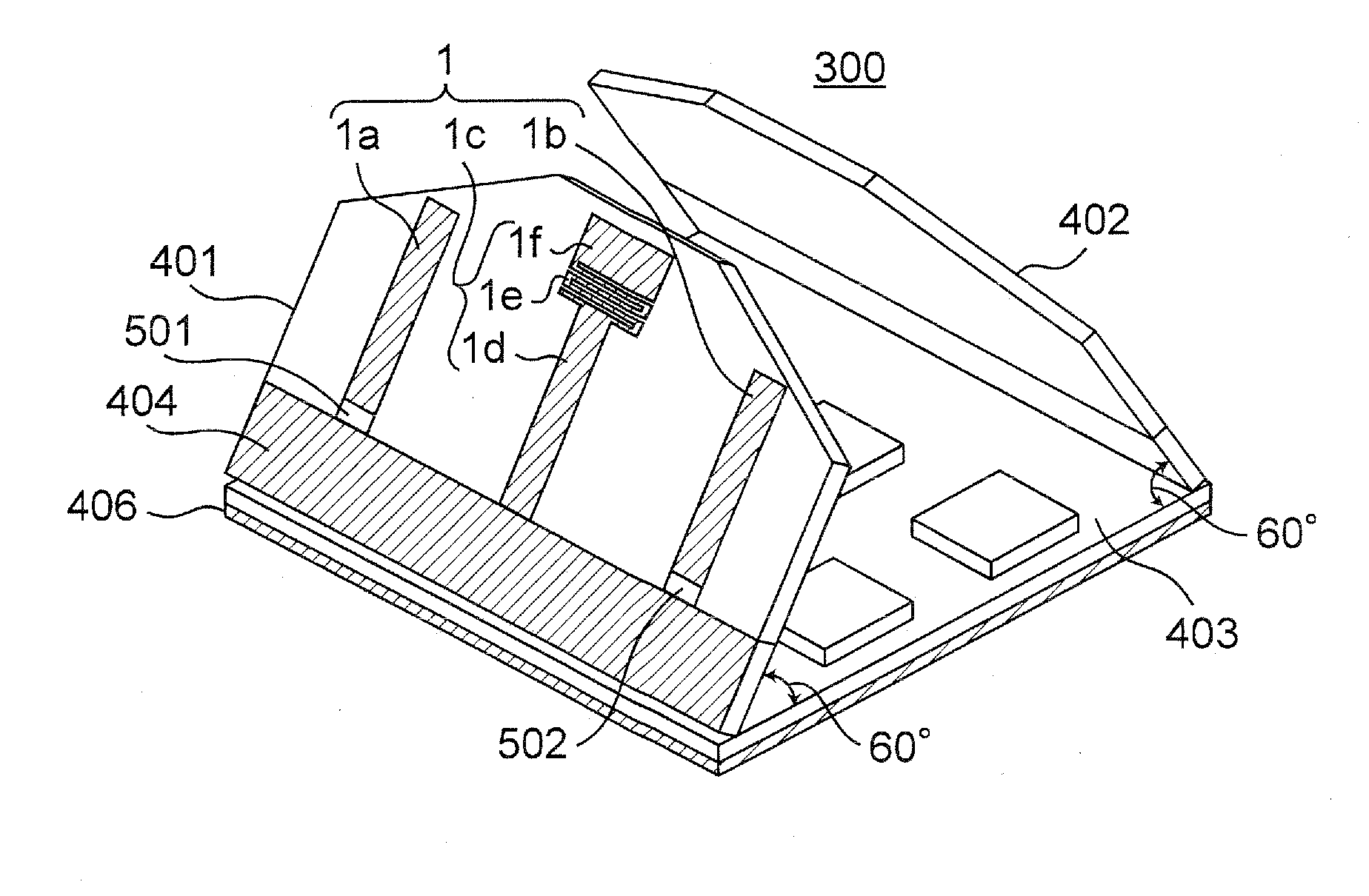
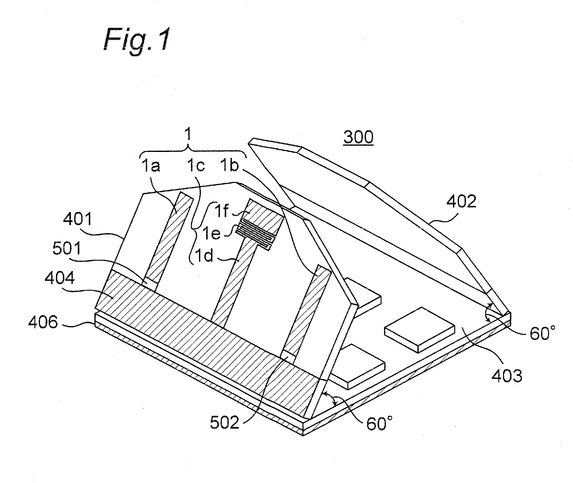
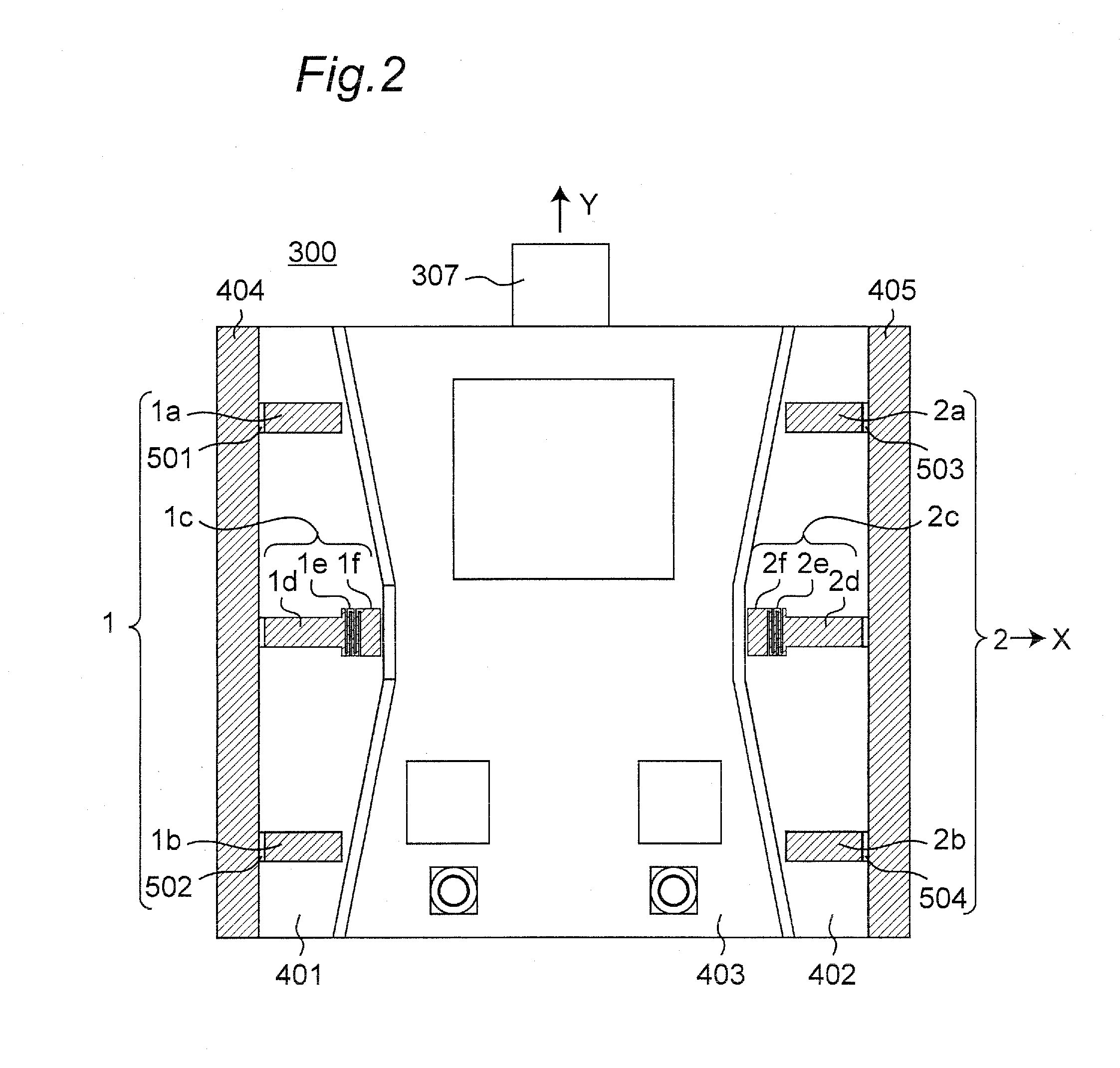
[0055]FIG. 1 is a perspective view showing an external appearance of a wireless communication apparatus 300 including a variable directivity antenna apparatus 1 of a type A0 according to one preferred embodiment of the present invention. FIG. 2 is a plan view of the wireless communication apparatus 300 of FIG. 1, and FIG. 3 is a block diagram showing an inner structure of the wireless communication apparatus 300 of FIG. 1.

[0056]Referring to FIGS. 1 to 3, the wireless communication apparatus 300 is, for example, a wireless communication apparatus of a 2×2 MIMO transmission system conforming to the wireless LAN communication standard IEEE802.11n. As shown in FIG. 2, the wireless communication apparatus 300 is configured to include variable direc...


PUM


Abstract

A feed element is configured to include a first antenna element having a first width, a dual-band forming inductor, and a second antenna element having a second width wider than the first width, where the first antenna element, the dual-band forming inductor, and a second antenna element are connected in series. The inductor is formed in a meander shape which has a trapezoidal envelope external shape to have a width formed to widen from the first width of a portion connected to the first antenna element toward a portion connected to the second antenna element. Cut portions each having a rectangular shape are further formed at corner portions of another ends of the parasitic elements, respectively.

Description

TECHNICAL FIELD[0001]The present invention relates to a variable directivity antenna apparatus having one feed element and at least one parasitic element.BACKGROUND ART[0002]Among network configurations in which information terminals are mutually connected, a wireless network that uses wireless communications has advantages over a wire network that uses wire communications in the following points. The wireless network has portability and the degree of freedom in the arrangement of the information terminals higher than those of the wire network, and can reduce the weights of the information terminals by removing wired cables. Thus, wireless communication apparatuses have been not only utilized for data transmission between conventional personal computers but also currently mounted in a lot of home electric appliances, and the wireless communication is utilized for video and audio data transmission among the home electric appliances.[0003]The wireless communication apparatuses has the...

Claims


Application Information

Patent Timeline
Patent Type & Authority Applications(United States)
IPC IPC(8): H01Q3/44H01Q19/28H01Q19/22H01Q5/10
CPCH01Q3/44H01Q5/321H01Q21/08
Inventor NOGUCHI, WATARUYURUGI, HIROYUKI
Owner PANASONIC CORP
Why Eureka
Try Eureka