Directional flat illuminators

a technology of illuminators and flats, applied in the field of light guides, can solve the problems of increased image crosstalk, non-uniform viewing windows, and limit the viewing freedom of the display, and achieve the effect of low loss

Active Publication Date: 2012-05-24
REALD SPARK LLC
View PDF9 Cites 318 Cited by
  • Summary
  • Abstract
  • Description
  • Claims
  • Application Information

AI Technical Summary

Benefits of technology

[0005]According to the present disclosure, a method for guiding light by employing an optical valve may allow light rays to propagate in a first direction through the optical valve, and the light may propagate in the first direction with substantially low loss. Additionally, the optical valve may allow the light rays to interact with an end surface of the optical valve and also may allow the light rays to propagate in a second direction through the optical valve, and while propagating in the second direction, at least some of the light rays may encounter at least one extraction feature and may be extracted from the optical valve.

Problems solved by technology

Gaps between the pixels, for example, for electrodes, typically produce non-uniform viewing windows.
Undesirably, such displays exhibit image flicker as an observer moves laterally with respect to the display and so limit the viewing freedom of the display.
Such flicker can be reduced by defocusing the optical elements; however such defocusing results in increased levels of image cross talk and increases visual strain for an observer.

Method used


Image

  • Directional flat illuminators
  • Directional flat illuminators
  • Directional flat illuminators

Examples


Embodiment Construction

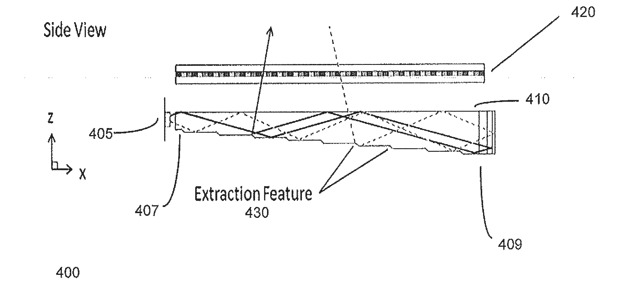
[0064]Generally, in the present disclosure, a method for guiding light by employing an optical valve may allow light rays to propagate in a first direction through the optical valve, and the light may propagate in the first direction with substantially low loss. Additionally, the optical valve may allow the light rays to interact with an end surface of the optical valve and also may allow the light rays to propagate in a second direction through the optical valve, and while propagating in the second direction, at least some of the light rays may encounter at least one extraction feature and may be extracted from the optical valve.

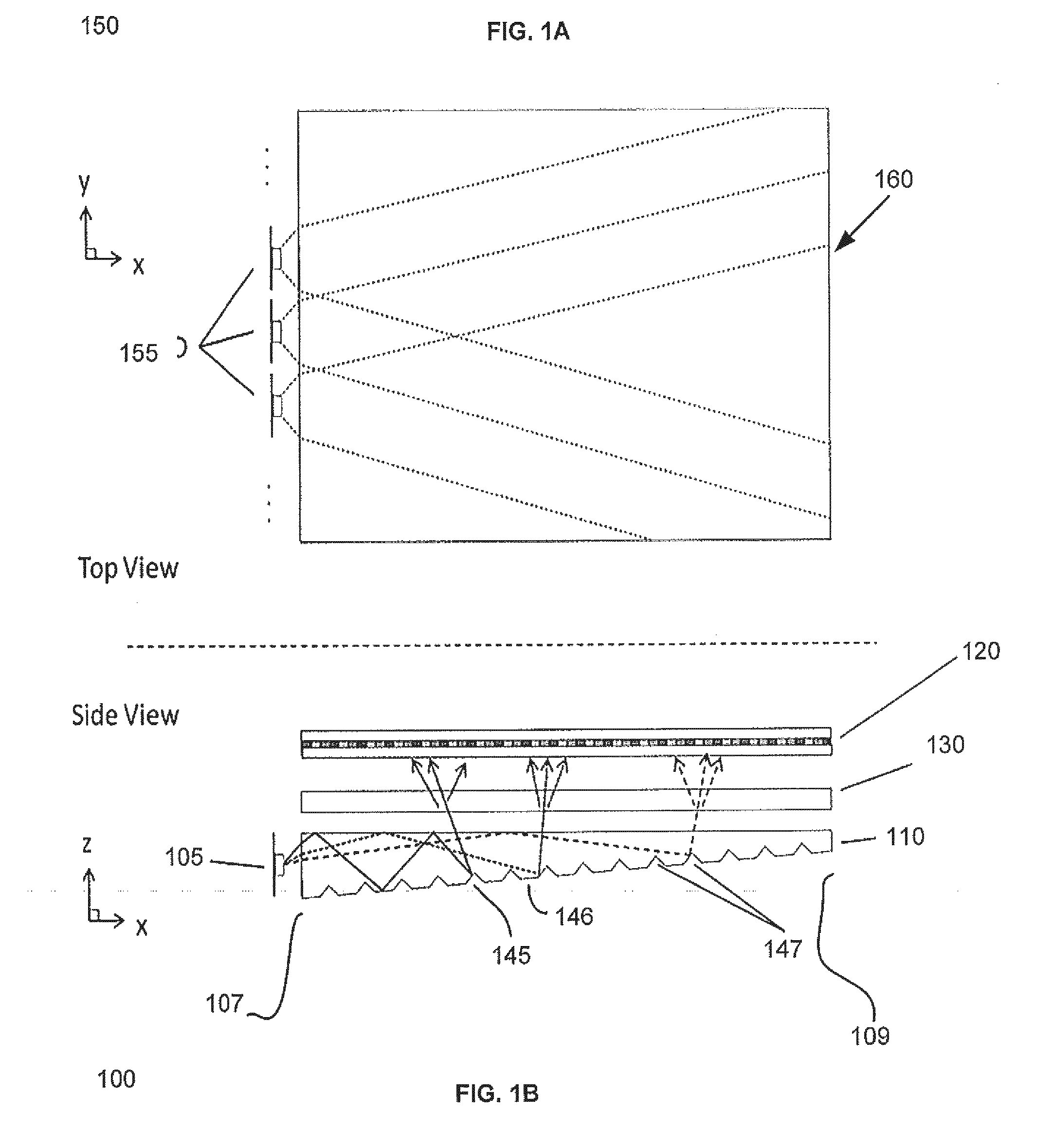
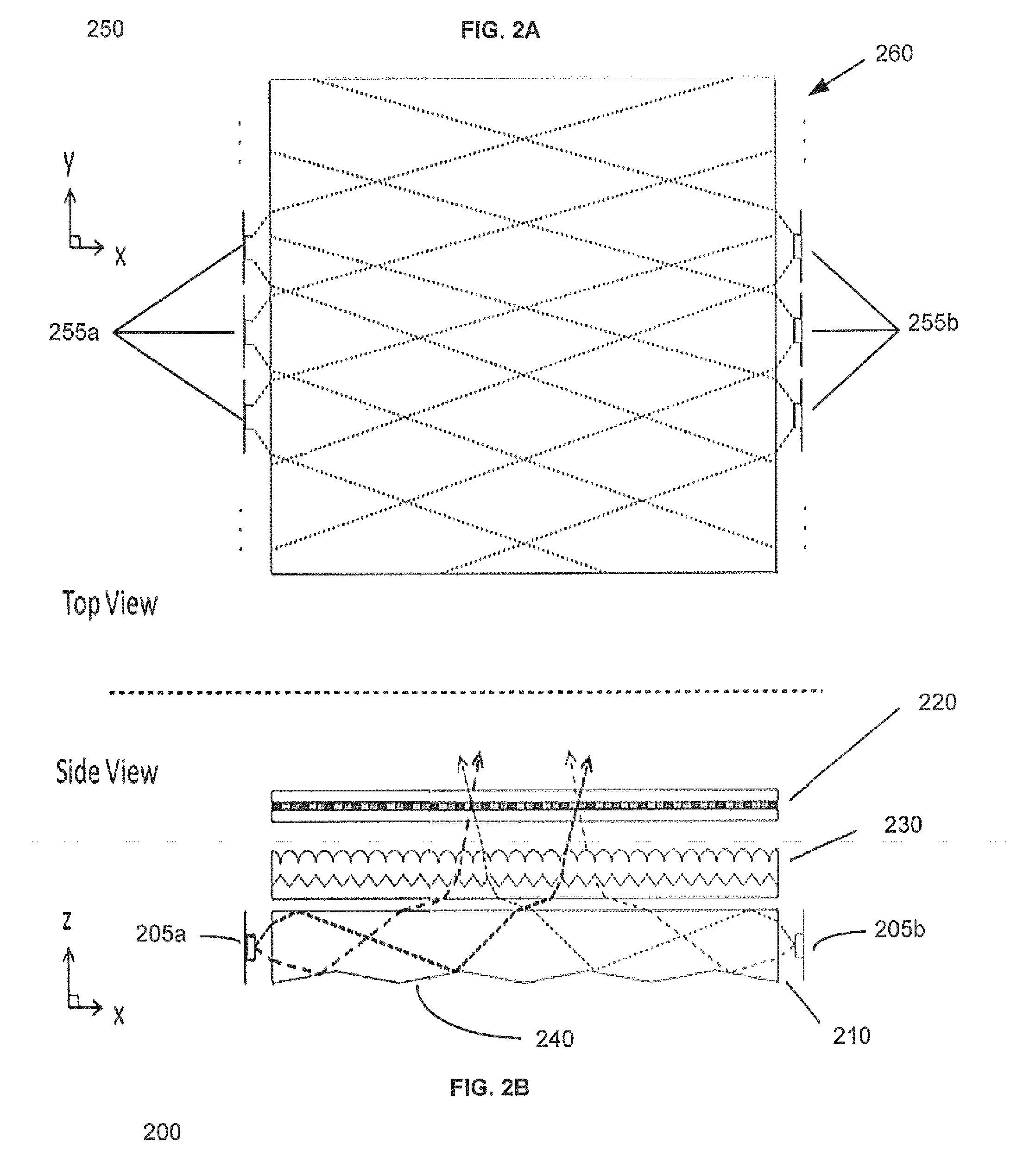
[0065]According to another aspect of the present disclosure, a light valve for guiding light, may include a first light guiding surface, wherein the first light guiding surface is substantially planar, and a second light guiding surface which may be opposite the first light guiding surface and may further include a plurality of guiding features and a plural...


PUM


Abstract

Disclosed is an optical valve or light valve for providing large area collimated illumination from localized light sources, and system and method thereof for 2D, 3D, and/or autosteroscopic displays. An optical valve may include a stepped structure, in which the steps include separated extraction features which may be optically hidden to light propagating in a first direction. Light propagating in a second direction may be refracted, diffracted, or reflected by the features to provide illumination beams exiting from the top surface of the optical valve. Such controlled illumination may provide for efficient, multi-user autostereoscopic displays as well as improved 2D display functionality.

Description

CROSS-REFERENCE TO RELATED APPLICATIONS[0001]This application claims priority to U.S. Provisional Patent Application No. 61 / 415,810, filed Nov. 19, 2010, entitled “Directional flat illuminators,” the entirety of which is herein incorporated by reference.TECHNICAL FIELD[0002]This disclosure generally relates to illumination of light modulation devices, and more specifically relates to light guides for providing large area directed illumination from localized light sources for use in 2D, 3D, and / or autostereoscopic display devices.BACKGROUND[0003]Spatially multiplexed autostereoscopic displays typically align a parallax component such as a lenticular screen or parallax barrier with an array of images arranged as a first and second set of pixels on a spatial light modulator. The parallax component directs light from each of the sets of pixels into different respective directions to provide first and second viewing windows in front of the display. An observer with an eye placed in the f...

Claims


Application Information

Patent Timeline
Patent Type & Authority Applications(United States)
IPC IPC(8): G02B27/22F21V7/04F21V8/00G02B30/33
CPCG02B6/0048G02B27/225G02B27/0093G02B6/0073H04N13/047G02B6/0046G02B6/0045H04N13/0411G02B6/0068H04N13/312H04N13/368H04N13/398G02B30/33G02B3/08G02B5/0205G02B30/36G02B6/004G02B6/0033G02B6/001G02B6/0038G02B6/005G02B6/0051G02B6/0055
Inventor ROBINSON, MICHAEL G.WOODGATE, GRAHAM JOHNHARROLD, JONATHAN
Owner REALD SPARK LLC
Why Eureka
Try Eureka